Dimmable LED driving circuit

An LED driver and circuit technology, applied in the semiconductor field, can solve the problems of instantaneous high voltage surge, LED lamp burnout, complex structure, etc., and achieve the effect of simplified structure, wide dimming range and easy use.

Inactive Publication Date: 2017-08-08
UNIV OF ELECTRONICS SCI & TECH OF CHINA
View PDF4 Cites 2 Cited by
  • Summary
  • Abstract
  • Description
  • Claims
  • Application Information

AI Technical Summary

Problems solved by technology

The LED lighting drive system includes rectification and constant current two parts, the structure is relatively complex, and the drive system is prone to instantaneous high-voltage surges, does not have the ability to protect large currents, and easily burns out the LED lights

Method used


Image

  • Dimmable LED driving circuit
  • Dimmable LED driving circuit
  • Dimmable LED driving circuit

Examples


Embodiment

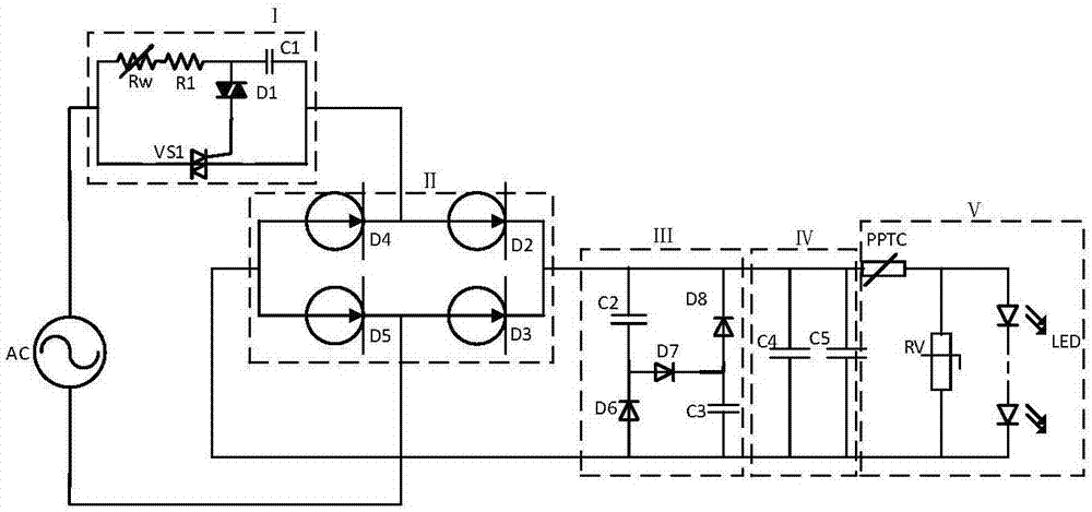
[0041] In this embodiment, the first high reverse withstand voltage constant current device D2, the second high reverse withstand voltage constant current device D3, the third high reverse withstand voltage constant current device D4 and the fourth high reverse withstand voltage constant current device Device D5 is the same high reverse withstand voltage constant current device. The structural schematic diagram of the high reverse withstand voltage constant current device is as follows Image 6 As shown, it includes a P-type lightly doped substrate 2, an N-type lightly doped epitaxial layer 3 located on the P-type lightly doped substrate 2, and a diffused P-type well located in the N-type lightly doped epitaxial layer 3. Region 4, the diffused P-type well region 4 is two and located at both ends, the P-type heavily doped region 5 and the N-type heavily doped region 7 located in the diffused P-type well region 4, located in the N-type heavily doped region The depletion channel...


PUM


Abstract

A dimmable LED driving circuit belongs to the technical field of a semiconductor. The LED constant-current driving circuit comprises a silicon controlled rectifier dimming module, a constant-current rectification module, a power factor correction module, a filtering module and a circuit protection module, wherein the silicon controlled rectifier dimming module is used for changing conduction delay and the size of a conduction angle by changing a RW resistance value of a dimming potentiometer so that the duty ratio of a current passing through an LED is changed to affect the brightness of the LED; the structure of a traditional LED driving circuit is simplified by the constant-current rectification module comprising a high-reverse voltage-resistant current-constant device, so that the rectification function and the constant-current function are combined, a mains supply can be directly connected without additionally arranging other discrete constant-current devices to drive an LED lamp string; and excessive large current passing through the LED is prevented by using a polymeric positive temperature coefficient (PPTC) thermistor, and the LED lamp string cannot be damaged due to transient high voltage by a piezoresistor Rv. By the LED constant-current driving circuit, the functions of rectification, constant current and dimming are combined, the structure of the driving circuit is simplified, the miniaturization of the driving system can be achieved, and the cost is reduced.

Description

technical field [0001] The invention belongs to the technical field of semiconductors, and in particular relates to a dimmable LED driving circuit. Background technique [0002] The constant current source is a commonly used electronic equipment and device, mainly used to protect the entire circuit, even if the voltage is unstable or the load resistance changes greatly, it can ensure the stability of the supply current. The constant current source has been used in electronic circuits. Widely used, such as the drive of LED light strings, etc. The traditional LED lighting driver is generally composed of a rectifier bridge plus one (or more) constant current chips or constant current devices. The constant current device is generally a constant current device similar to a JFET junction field effect transistor structure, with bidirectional conduction The characteristic is that it can achieve the effect of constant current when it works in the forward direction, and it is similar...

Claims


Application Information

Patent Timeline
Patent Type & Authority Applications(China)
IPC IPC(8): H05B33/08H05B44/00
CPCH05B45/10H05B45/37Y02B20/30
Inventor 乔明李路宋旭朱旭晗于亮亮梁龙飞张波
Owner UNIV OF ELECTRONICS SCI & TECH OF CHINA
Why Eureka
Try Eureka