
Anti-rotary device of single oil cylinder support boot

An anti-rotation and oil cylinder technology, which is applied in fluid pressure actuators, mining equipment, earthwork drilling and mining, etc., can solve the problems of tail shield scrapping, construction efficiency reduction, and wear of the inner wall of the tail shield, so as to avoid inner surface wear and ensure Efficiency and quality, the effect of reducing the chance of segment sealing

Pending Publication Date: 2017-08-11
CHINA RAILWAY ENGINEERING EQUIPMENT GROUP CO LTD
View PDF6 Cites 8 Cited by
  • Summary
  • Abstract
  • Description
  • Claims
  • Application Information

AI Technical Summary

Problems solved by technology

During the propulsion or contraction process of the single oil cylinder in the active articulated shield machine, due to its own internal structural problems and partial load, the shoe will rotate, causing the shoe to scrape against the inner shell of the shield tail. Long-term wear will cause deep grooves on the inner wall of the tail shield, and at the same time, the boot plate will be rolled onto the segment sealing strip, causing the segment seal to be easily damaged, resulting in unnecessary economic losses and construction Reduced efficiency
[0003] At present, the solution adopted by various manufacturers to prevent the deflection of a single oil cylinder is: to weld the anti-rotation block on the support shoe, although this can prevent the rotation of a single oil cylinder, but the anti-rotation block pushes the inner shell of the tail shield for a long time, will wear out the inner shell of the tail shield into deep pits
During the push of a single oil cylinder, the friction between the anti-rotation block and the inner casing of the tail shield will also wear out deep grooves in the inner casing of the tail shield, causing damage to the tail shield, and in severe cases, it will cause shield scrapping

Method used


Image

  • Anti-rotary device of single oil cylinder support boot
  • Anti-rotary device of single oil cylinder support boot
  • Anti-rotary device of single oil cylinder support boot

Examples


Embodiment Construction

[0029] In describing specific embodiments of the present invention, it should be understood that the terms "center", "longitudinal", "transverse", "upper", "lower", "front", "rear", "left", " The orientation or positional relationship indicated by "right", "vertical", "horizontal", "top", "bottom", "inner", "outer", etc. is based on the orientation or positional relationship shown in the drawings, and is for convenience only The present invention is described and simplified descriptions do not indicate or imply that the device or element referred to must have a specific orientation, be constructed and operate in a specific orientation, and thus should not be construed as limiting the present invention. In addition, the terms "first", "second", etc. are used for descriptive purposes only, and should not be understood as indicating or implying relative importance or implicitly specifying the quantity of the indicated technical features. Thus, a feature defined as "first", "secon...


PUM


Abstract

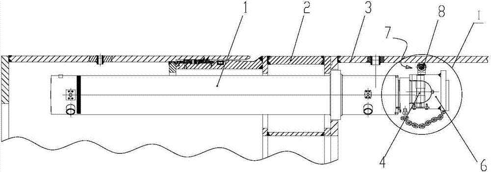
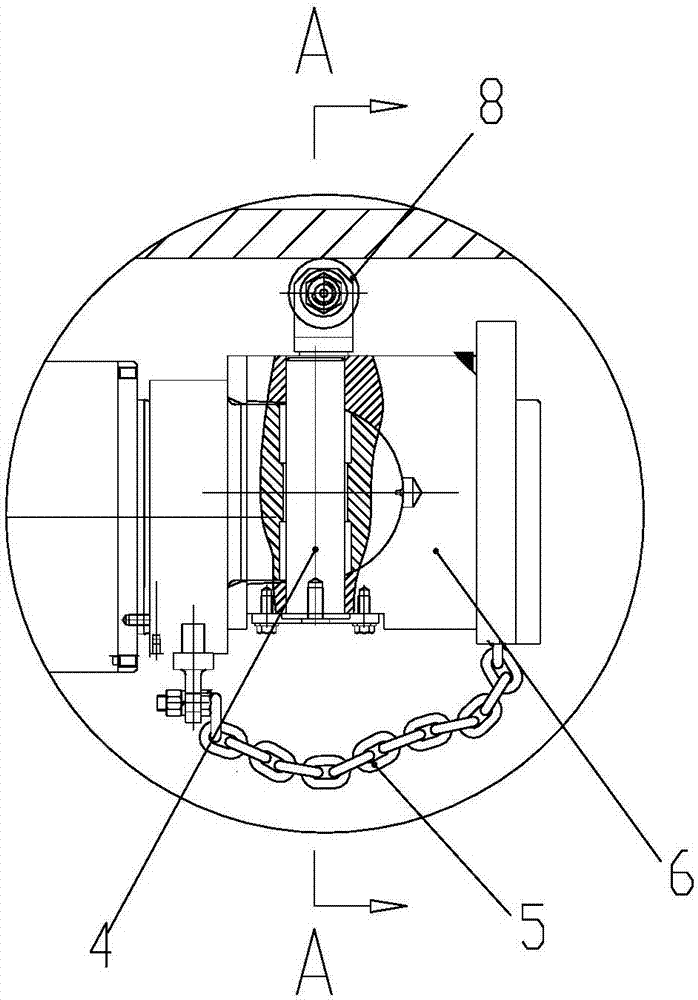
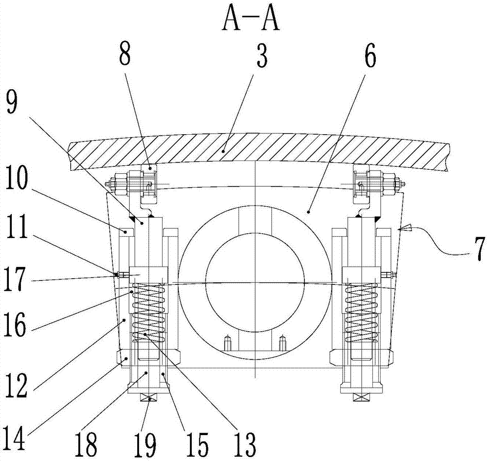
The invention discloses an anti-rotary device of a single oil cylinder support boot. The anti-rotary device comprises an oil cylinder arranged between a middle shield and a tail shield in a connected mode, the support boot is arranged at the front end of a piston rod of the oil cylinder in a connected mode, and anti-rotary mechanisms are symmetrically arranged, at the two sides of the left-right symmetrical center line of the support boot, on the support boot; and each anti-rotary mechanism comprises a supporting piece and a keeping piece, wherein each supporting piece extends out the upper surface of the support boot and is matched with the inner surface of the tail shield in a contact mode, and each keeping piece is arranged on the support boot and drives the corresponding supporting piece and the inner surface of the tail shield to be kept in close contact elastically. According to the anti-rotary device of the single oil cylinder support boot, the supporting pieces at the left and right sides support at two left-right symmetrical points of the support boot, can be kept in close contact with the inner surface of the tail shield, and both generate rolling friction with the inner surface of the tail shield, rolling fraction force is large, rotating of the support boot is prevented effectively, it is ensured that the support boot cannot scratch the inner surface of the tail shield, the support boot cannot be in contact with duct piece seal, the probability of damage of the duct piece seal due to pushing is reduced, and the efficiency and quality of duct piece assembling is guaranteed.

Description

technical field [0001] The invention belongs to the field of tunnel boring machine equipment, in particular to an anti-rotation device for a single oil cylinder support shoe. Background technique [0002] At present, the shield machines used in the tunnel construction process can be divided into two types according to their articulated forms: active articulated shield machines and passive articulated shield machines. The active articulated shield machine has more advantages than the passive articulated shield machine, so it is widely used. During the propulsion or contraction process of the single oil cylinder in the active articulated shield machine, due to its own internal structural problems and partial load, the shoe will rotate, causing the shoe to scrape against the inner shell of the shield tail. Long-term wear will cause deep grooves on the inner wall of the tail shield, and at the same time, the boot plate will be rolled onto the segment sealing strip, causing the ...

Claims


Application Information

Patent Timeline
Patent Type & Authority Applications(China)
IPC IPC(8): E21D9/06F15B15/20
CPCF15B15/20
Inventor 侯志富刘晓宇高文梁董亚岭闫永阵王昆
Owner CHINA RAILWAY ENGINEERING EQUIPMENT GROUP CO LTD
Learn More