Vertical-ring high-gradient magnetic separator

A high-gradient magnetic separator and vertical ring technology, applied in the direction of high-gradient magnetic separator, etc., can solve the problems such as the improvement of the separation magnetic field and the adverse effect of stability, the gas is not easily discharged, and the heat dissipation effect, etc., and is conducive to oil circulation. And the effect of gas discharge, improved heat dissipation effect, improved stability and service life

Active Publication Date: 2017-08-15
SHANDONG HUATE MAGNET TECH
View PDF6 Cites 3 Cited by
  • Summary
  • Abstract
  • Description
  • Claims
  • Application Information

AI Technical Summary

Problems solved by technology

At present, the diameter of the sorting swivel of the forced oil-cooled vertical ring high-gradient magnetic separator has reached more than 5 meters. Due to the large cross-section of the excitation coil of the large-scale vertical ring high-gradient magnetic separator, the excitation coils of the coil are arranged horizontally , its disadvantages are: although there are horizontally arranged oil passages between the coils, due to the long flow passages and small gaps, the oil flow speed becomes slow, the gas is not easy to discharge, the heat exchange is slow after the oil temperature rises, and the internal and external temperature difference is large. , the heat dissipation effect is affected to a certain extent, which has an adverse effect on the improvement and stability of the sorting magnetic field

Method used


Image

  • Vertical-ring high-gradient magnetic separator
  • Vertical-ring high-gradient magnetic separator
  • Vertical-ring high-gradient magnetic separator

Examples


Embodiment Construction

[0030] The present invention will be described in detail below with reference to the accompanying drawings and examples.

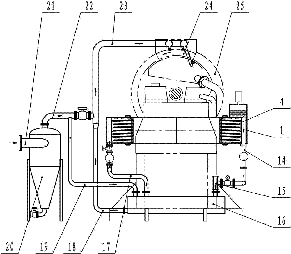
[0031] Such as figure 1 As shown, the vertical ring high gradient magnetic separator of the present invention includes a cooling system and an ore flushing system.

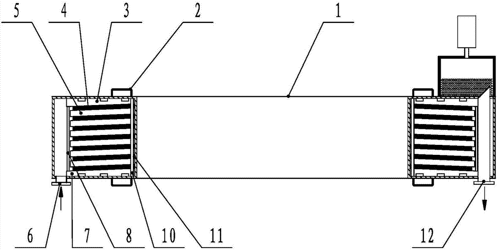
[0032] Such as figure 1 As shown, wherein, the cooling system includes: an excitation coil, an oil pump 15 and a cooler, and the cooler adopts an oil-water heat exchanger 16, and the excitation coil, the oil pump 15, and the oil-water heat exchanger 16 are connected in series through an oil inlet pipe 17 and an oil outlet pipe 14 Form a closed forced oil circulation loop.

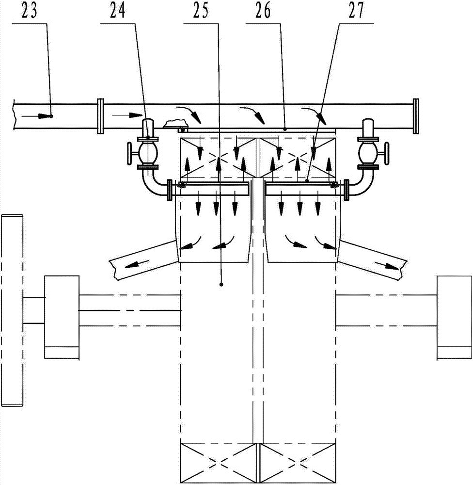
[0033] Such as figure 1 and figure 2 Commonly shown, wherein, the ore flushing system includes: ore flushing water pipe, the ore flushing water pipe is divided into a flushing ore water pipe 23 and a recoil ore water pipe 24 at its water outlet, and the flushing ore water pipe 23 is located at the end of the vertical r...


PUM


Abstract

The invention discloses a vertical-ring high-gradient magnetic separator which comprises a cooling system and a mineral flushing system; the cooling system comprises a magnet exciting coil, an oil pump and a cooler; the mineral flushing system comprises a filter and a mineral flushing water pipe; the mineral flushing water pipe comprises a positive mineral flushing water pipe located on the outer side of the upper part of a revolving ring, and a negative mineral flushing water pipe located on the inner side of the upper part of the revolving ring; the magnet exciting coil comprises magnet exciting wire coils arranged in an inner cavity of a coil case; each magnet exciting wire coil is obliquely arranged in a vertically multilayer manner; the outer circumference of each magnet exciting wire coil is higher than the inner circumference of the magnet exciting wire coil; interlayer insulation filler strips are arranged among gaps of each magnet exciting wire coil in a spaced manner, and interlayer cooling liquid channels are formed; inner holes of the coil case are in waist drum shapes; and two oil inlets are formed in one end of the coil case and two oil outlets are formed in the other end of the coil case. The vertical-ring high-gradient magnetic separator is high in oil flowing speed, good in heat dissipation effect, and good in mineral flushing effect; the problem that vibration friction is generated when the magnet exciting coil is electrified is solved; the stability and the service life of the magnet exciting coil is improved and prolonged; and the requirements of the large vertical-ring high-gradient magnetic separator are met fully.

Description

technical field [0001] The invention relates to the technical field of mineral processing equipment, in particular to a vertical ring high-gradient magnetic separator. Background technique [0002] At present, in mineral separation and processing equipment, wet vertical ring high gradient magnetic separator has been widely used, mainly in small and medium-sized ones. Its cooling methods are mainly water cooling and oil cooling. Since the water cooling uses hollow electromagnetic wires to pass water inside, the cross-section of the flow channel is small, the flow rate is small, and the requirements for water quality are high. Otherwise, it is easy to form a blockage, so it is subject to certain restrictions in use. . The forced oil cooling vertical ring high gradient magnetic separator adopts a closed shell, the coil is soaked in transformer oil, and there is a horizontal oil flow gap between the coils of each layer, and the external circulation is used to cool the coil, whi...

Claims


Application Information

Patent Timeline
Patent Type & Authority Applications(China)
IPC IPC(8): B03C1/025B03C1/031
CPCB03C1/025B03C1/031
Inventor 王兆连贾洪利刘凤亮吴海双
Owner SHANDONG HUATE MAGNET TECH
Why Eureka
Try Eureka