
Touch display panel and manufacturing method thereof, and display device

A technology of a touch display panel and a manufacturing method, which are applied in the fields of display devices, touch display panels and manufacturing methods thereof, can solve the problems of inability to form an electrostatic discharge path, reduced ESD resistance, and risk of debris, and achieve an electrostatic discharge path. Stabilizing, improving antistatic ability, preventing the effect of debris risk

Inactive Publication Date: 2017-08-15
XIAMEN TIANMA MICRO ELECTRONICS
View PDF5 Cites 5 Cited by
  • Summary
  • Abstract
  • Description
  • Claims
  • Application Information

AI Technical Summary

Problems solved by technology

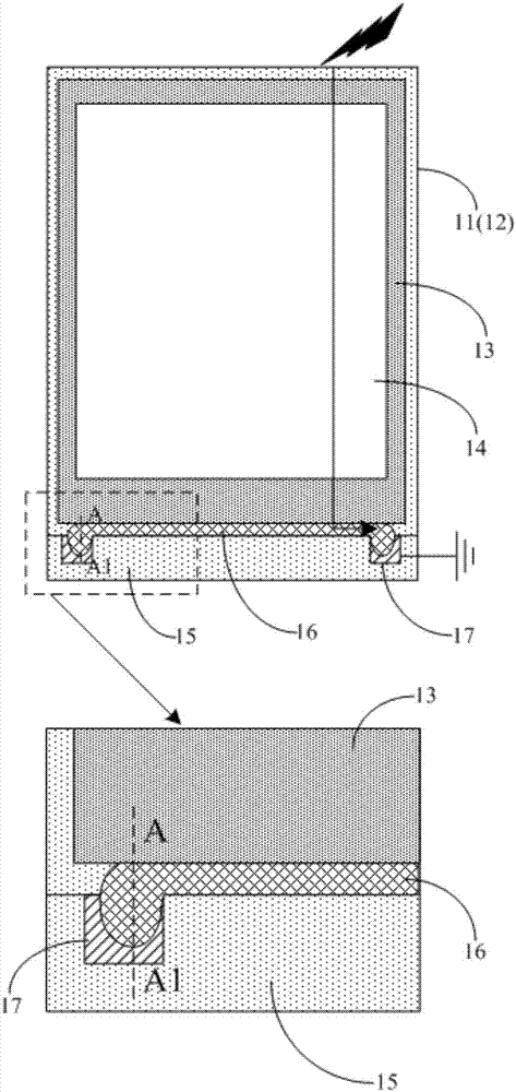
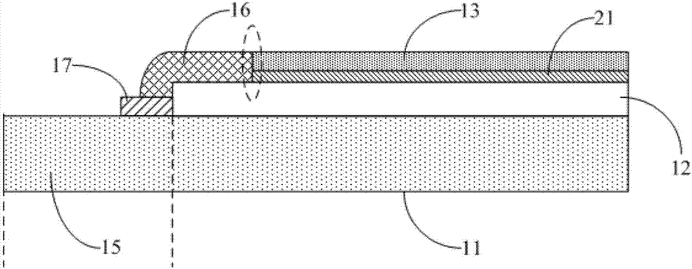
[0007] First, the silver glue 16 is in side contact with the conductive glue layer 21, and the contact area is small, such as figure 2 As shown, when the process deviates in the production process, the silver glue 16 and the conductive glue layer 21 will not be in contact, as in the dotted line area in the figure, the silver glue 16 and the conductive glue layer 21 will be disconnected. Unable to form an electrostatic discharge path, and the ability to resist ESD is reduced
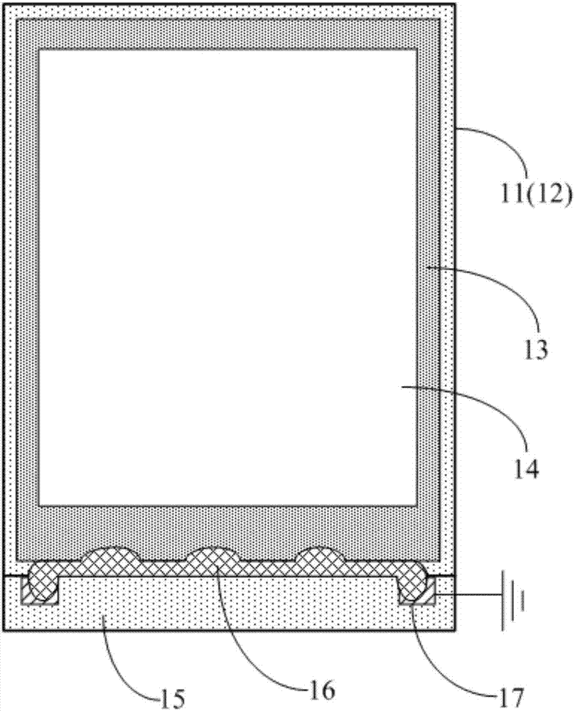
[0008] Second, if image 3 as shown, image 3 It is a schematic plan view of another touch display panel in the prior art. When there is a deviation in the production process, there may be a situation where the silver glue 16 is coated on the top of the polarizer 13. When the silver glue 16 is coated on the top of the polarizer 13 , there is a risk of fragmentation in the actual production process

Method used


Image

  • Touch display panel and manufacturing method thereof, and display device
  • Touch display panel and manufacturing method thereof, and display device
  • Touch display panel and manufacturing method thereof, and display device

Examples


Embodiment Construction

[0040] Embodiments of the present invention provide a touch display panel, a manufacturing method thereof, and a display device, which are used to improve the antistatic ability of the touch display panel and prevent the risk of debris.

[0041]In order to make the purpose, technical solutions and advantages of the present invention clearer, the present invention will be further described in detail below in conjunction with the accompanying drawings. Obviously, the described embodiments are only some of the embodiments of the present invention, rather than all of them. Based on the embodiments of the present invention, all other embodiments obtained by persons of ordinary skill in the art without making creative efforts belong to the protection scope of the present invention.

[0042] The touch display panel provided by specific embodiments of the present invention will be described in detail below in conjunction with the accompanying drawings.

[0043] The thickness, area siz...


PUM

PropertyMeasurementUnit
Thicknessaaaaaaaaaa

Abstract

The invention discloses a touch display panel and a manufacturing method thereof, and a display device, aiming at improving the antistatic ability of the touch display panel and preventing the risk of fragments. The touch display panel comprises an array substrate and a subtended substrate which are arranged opposite to each other, a first polaroid arranged at the side, opposite to the subtended substrate, of the array substrate, a second polaroid positioned at the side, opposite to the array substrate, of the subtended substrate, a grounding electrode arranged on the array substrate, at least one conductive bar and a conductive connecting piece; the part of the conductive bar is exposed, and the exposed conductive bar is electrically connected with the grounding electrode by the conductive connecting piece; the conductive bar is positioned between the first polaroid and the array substrate, and the orthographic projection area of the conductive bar on the array substrate is positioned in a non-display area of the array substrate; and / or, the conductive bar is positioned between the second polaroid and the subtended substrate, and the orthographic projection area of the conductive bar on the subtended substrate is positioned in a non-display area of the subtended substrate.

Description

technical field [0001] The present invention relates to the field of display technology, in particular to a touch display panel, a manufacturing method thereof, and a display device. Background technique [0002] With the rapid development of display technology, touch display panels (Touch Panel) have gradually spread in people's lives. Compared with the traditional display which can only provide the display function, the display using the touch display panel can enable information interaction between the user and the display control host. At present, the most widely used touch display panel is the capacitive touch display panel. The capacitive touch display panel is divided into internal Embedded (in-cell), external embedded (on-cell) and plug-in three. Among them, the in-cell capacitive touch display panel is an important development direction of touch technology due to its advantages of high integration, thin profile, and superior performance. [0003] Prior art in-cel...

Claims


Application Information

Patent Timeline
IPC IPC(8): G06F3/041G06F3/044
CPCG06F3/041G06F3/044G06F2203/04103
Inventor 吴昊
Owner XIAMEN TIANMA MICRO ELECTRONICS
Learn More