A millimeter wave array antenna design method and array antenna device

A technology of array antenna and design method, which is applied in the direction of antenna, antenna array, design optimization/simulation, etc., can solve problems such as the inability to effectively solve the mutual coupling phenomenon of array antenna elements, and achieve the effect of automatic optimal design

Active Publication Date: 2019-12-13
UNIV OF SCI & TECH BEIJING
View PDF2 Cites 0 Cited by
  • Summary
  • Abstract
  • Description
  • Claims
  • Application Information

AI Technical Summary

Problems solved by technology

[0004] The technical problem to be solved by the embodiments of the present invention is that the mutual coupling phenomenon of array elements in the array antenna cannot be effectively solved. In view of the above technical problems, an optimized array element synthesis method is proposed, and the antenna radiation pattern obtained by the simulation software is used instead of the array factor The pattern is used as the target pattern, the feed network is pre-designed, and the structural parameters of the feed network are equivalent to the feed current of the array element to directly obtain the structural parameters of the antenna; through the design of the objective function and the optimization simulation process to Control the direction and speed of algorithm optimization during array synthesis, so as to realize the joint simulation of antenna radiation pattern and optimization algorithm. In the process of array synthesis, the influence of mutual coupling factors is considered, and the final result does not require coupling compensation, and through simulation saves cost and simplifies the design process

Method used


Image

  • A millimeter wave array antenna design method and array antenna device
  • A millimeter wave array antenna design method and array antenna device
  • A millimeter wave array antenna design method and array antenna device

Examples


no. 1 example

[0038] This embodiment provides a method for designing a millimeter-wave array antenna. The objective function is designed through the design index of the array antenna, and the optimization algorithm searches for an optimal solution of the physical size of the impedance converter along the direction of the objective function. The fitness value is calculated by using the antenna radiation pattern simulated by the high-frequency structure simulation software to obtain the optimal objective value function. Specifically, the millimeter-wave array antenna design method of this embodiment includes the following steps:

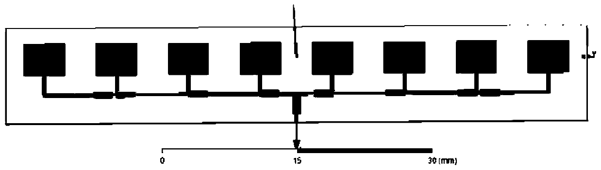
[0039] Step S101, designing the array element and the feeding network, and obtaining the structural parameters of the array antenna model.

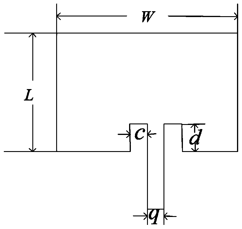
[0040] Preferably, the array elements in this step adopt plug-in feeding. The plug-in feeding method refers to slotting at the contact between the feeder line and the radiation edge of the patch to adjust the impedance matchin...

no. 2 example

[0126] This embodiment provides a millimeter-wave array antenna device. The device is designed and assembled according to the steps of the first embodiment, so as to obtain a millimeter-wave array antenna that does not require coupling compensation, which saves costs and simplifies design. process.

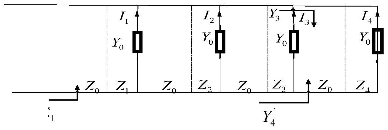
[0127] The millimeter-wave array antenna device at least includes a millimeter-wave array antenna and a feeding network, wherein the millimeter-wave array antenna is composed of several element antennas, and the structural parameters of the feeding network and the feeding current of the element antennas are Equivalently, the current distribution to each array element antenna can be realized by adjusting the physical size of the impedance changer of the feed network, so that the millimeter wave array antenna device has an ideal antenna pattern.

[0128] The millimeter-wave array antenna device described in this embodiment is implemented by joint simulation of matlab and HFSS, which...


PUM


Abstract

The invention provides a millimeter wave array antenna design method and an array antenna device. The design method comprises the following steps of: firstly designing an array model with a feed network, and enabling structure parameters of the feed network to be equivalent to feed current of an array element, so as to directly solve structure parameters of an antenna during array synthesis; replacing a factor directional diagram by a radiation directional diagram of an antenna array, designing a target function through design indexes of the array antenna, and searching an optimum solution of the physical size of an impedance transformer along the direction of the target function via an optimization algorithm. According to the method, the influences of cross-coupling factors are considered in the array synthesis process, the final result does not need coupling compensation, and a simulation manner is adopted to save the cost and simplify the design process. By adoption of joint simulation, a lot of fussy work in the design optimization process of the array antenna is avoided, and the automatic design of the antenna is achieved.

Description

technical field [0001] The invention belongs to the technical field of wireless communication, and in particular relates to a millimeter wave array antenna design method and an array antenna device. Background technique [0002] With the rapid development of wireless Internet, microwave spectrum resources are increasingly scarce. In order to accommodate more users, the future 5G system will expand to the millimeter wave frequency band. An interface for utilizing spectrum resources, that is, an antenna, is an important part of a wireless communication system. While spectrum resources are expanding to the millimeter wave frequency band, correspondingly, in-depth research on antennas in the millimeter wave frequency band is also required. Compared with microwave, the wavelength of millimeter wave is shorter, and the number of millimeter wave antennas can be more in the same physical area. The millimeter-wave antenna is an array antenna, which has the following advantages: the...

Claims


Application Information

Patent Timeline
Patent Type & Authority Patents(China)
IPC IPC(8): G06F17/50H01Q21/00
CPCG06F30/20H01Q21/00Y02E60/00
Inventor 陈月云赵庸旭马帅帅
Owner UNIV OF SCI & TECH BEIJING
Why Eureka
Try Eureka