Equipment for applying ultrasonic cutting to powder laying type additional and subtractive composite manufacturing and machining method

A technology of ultrasonic cutting and processing method, which is applied in the field of additive and subtractive material manufacturing, can solve the problems that affect the service life of the tool, the machining accuracy and surface quality of the workpiece, the heat cannot be taken away in time, and the cutting fluid cannot be used, etc., achieving significant social benefits, The effect of novel structure, improving processing accuracy and quality

Inactive Publication Date: 2017-08-18
DALIAN UNIV OF TECH
View PDF6 Cites 22 Cited by
  • Summary
  • Abstract
  • Description
  • Claims
  • Application Information

AI Technical Summary

Problems solved by technology

In addition, because the traditional cutting fluid will affect the additive manufacturing process, the cutting fluid cannot be used in the entire process of adding and subtracting materials, so that the heat generated by cutting cannot be taken away in time, which further increases the temperature rise of the cutting edge of the tool. These problems are all Seriously affect the service life of the tool and the machining accuracy and surface quality of the workpiece in the subsequent material reduction process

Method used


Image

  • Equipment for applying ultrasonic cutting to powder laying type additional and subtractive composite manufacturing and machining method
  • Equipment for applying ultrasonic cutting to powder laying type additional and subtractive composite manufacturing and machining method
  • Equipment for applying ultrasonic cutting to powder laying type additional and subtractive composite manufacturing and machining method

Examples


Embodiment Construction

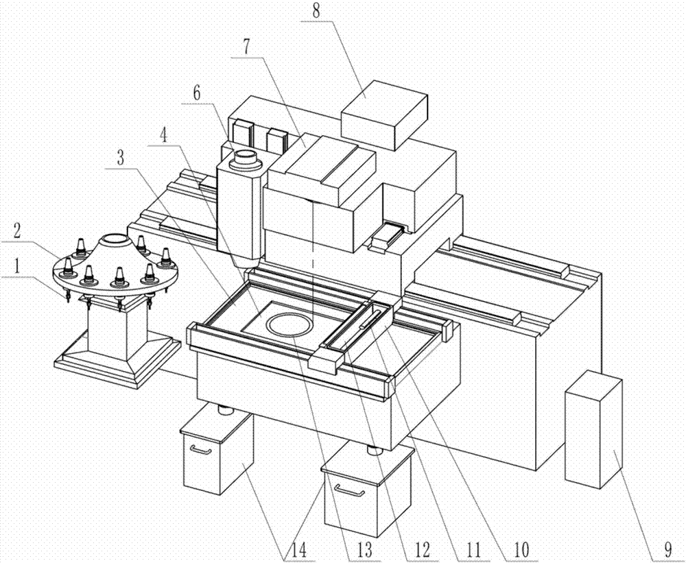
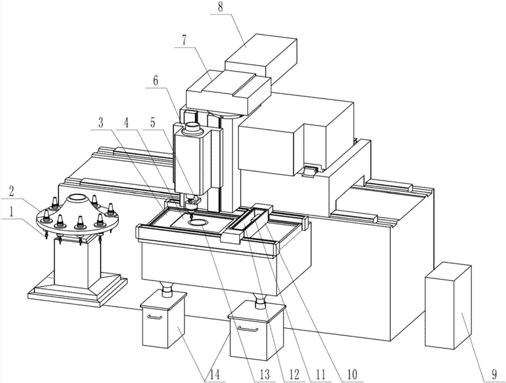
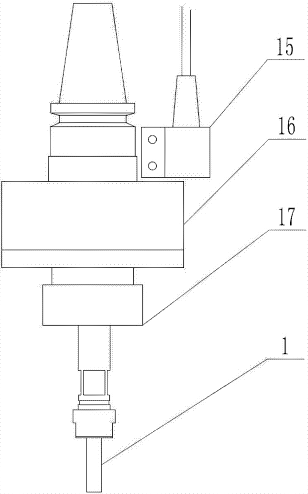
[0037] The specific embodiment of the present invention is shown in the accompanying drawings. The equipment that applies ultrasonic cutting to powder-spreading type additive and subtractive material composite manufacturing includes: tool 1, tool magazine 2, workbench 3, bed, spindle 6, and laser scanning system 7 , a laser generator 8, a powder supply device 9, a powder spreading device, an ultrasonic cutting device 5 and a powder recovery device 14; the workbench 3 is installed in the middle of the front of the bed and arranged horizontally, and there is a molding cavity in the workbench 3 4. The molding cavity 4 can move up and down in the vertical direction, and the substrate can be installed in the molding cavity 4, and the composite manufacturing of adding and subtracting materials is carried out on the substrate; the powder spreading device is installed on the workbench 3 and is located at one end of the workbench 3 ; The laser generator 8 and the laser scanning system 7...


PUM


Abstract

The invention relates to the field of additional and subtractive manufacturing, in particular to equipment for applying ultrasonic cutting to powder laying type additional and subtractive composite manufacturing and a machining method. A workbench is horizontally installed in the middle position of the front portion of a lathe bed. A molding cavity is formed in the workbench and can move up and down in the vertical direction. A base plate can be installed in the molding cavity. Additional and subtractive composite manufacturing is carried out on the base plate. A powder laying device is installed on the workbench and located at one end of the workbench. A laser generator and a laser screening system are fixed to the position over the front portion of the lathe bed. A powder supply device is located on the outer side of the lathe bed. A magazine tool is located on one side of the front portion of the lathe bed. A tool is installed in the magazine tool. A main shaft is installed on the front portion of the lathe body, and can slide along sliding rails in the X,Y and Z directions. During additional manufacturing, the main shaft is located at one end of the workbench. During subtractive machining, the main shaft moves to the position over the workbench. The tool is installed on the lower portion of the main shaft, and an ultrasonic cutting device is installed between the tool and the main shaft. A powder recycling device is arranged on the lower portion of the workbench.

Description

technical field [0001] The invention relates to the field of additive and subtractive material manufacturing, in particular to a device and a processing method for applying ultrasonic cutting to powder-spreading additive and subtractive material composite manufacturing. Background technique [0002] The traditional manufacturing process of metal parts mainly removes raw materials through mechanical subtractive processing methods such as turning and milling, and finally obtains parts that meet the quality and precision requirements, which not only wastes materials but also makes it difficult to process parts with complex curved surfaces; additive manufacturing is Discretize the three-dimensional entity into several two-dimensional planes, and produce three-dimensional parts by superimposing materials layer by layer, which can effectively reduce the waste of raw materials, and can process complex parts of any shape. The disadvantage is that the surface quality of the workpiece ...

Claims


Application Information

Patent Timeline
Patent Type & Authority Applications(China)
IPC IPC(8): B22F3/105B33Y10/00B33Y30/00
CPCB22F3/003B33Y10/00B33Y30/00B22F10/00B22F10/28B22F12/22B22F10/50Y02P10/25
Inventor 白倩张璧杨秀轩
Owner DALIAN UNIV OF TECH
Why Eureka
Try Eureka