Cutting machine for metal corrugated pipes

A cutting machine and corrugation technology, applied in the field of cutting machines for metal corrugated pipes, can solve the problem that the cutting machine cannot automatically feed materials, etc., and achieve the effects of improving productivity, speeding up work progress and increasing work efficiency

Inactive Publication Date: 2017-08-18
何朋飞
View PDF6 Cites 12 Cited by
  • Summary
  • Abstract
  • Description
  • Claims
  • Application Information

AI Technical Summary

Problems solved by technology

[0004] The purpose of the present invention is to provide a cutting machine for metal bellows, which has the advantage of automatic feeding and solves the problem that common cutting machines cannot automatically feed

Method used


Image

  • Cutting machine for metal corrugated pipes
  • Cutting machine for metal corrugated pipes
  • Cutting machine for metal corrugated pipes

Examples


Embodiment Construction

[0016] The following will clearly and completely describe the technical solutions in the embodiments of the present invention with reference to the accompanying drawings in the embodiments of the present invention. Obviously, the described embodiments are only some, not all, embodiments of the present invention. Based on the embodiments of the present invention, all other embodiments obtained by persons of ordinary skill in the art without making creative efforts belong to the protection scope of the present invention.

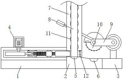
[0017] see figure 1 , a cutting machine for metal bellows, comprising a bearing table 1, a cutting table 2 and a cutting machine base 3, the top of the bearing table 1 is fixedly connected with an ejection mechanism 4, and the top of the cutting table 2 is sequentially provided with a discharge mechanism from left to right. Groove 5 and cutting groove 6, the horizontal plane at the bottom of the inner wall of the discharge chute 5 is higher than the horizontal...


PUM


Abstract

The invention discloses a cutting machine for metal corrugated pipes. The cutting machine for the metal corrugated pipes comprises a bearing table, a cutting table and a cutting machine base. The top of the bearing table is fixedly connected with a jacking mechanism. The top of the cutting table is provided with a discharging groove and a cutting groove sequentially from left to right. The position, corresponding to the discharging groove, of the top of the cutting table is fixedly connected with a feeding shell. A discharging channel is formed in the bottom of the side, close to the cutting groove, of the feeding shell. The top of the cutting machine base is fixedly connected with a cutting machine body. A cutting wheel is arranged in the position, corresponding to the discharging groove, of the cutting machine body. Through cooperation of the jacking mechanism, the discharging groove, the cutting groove, the feeding shell and the discharging channel, an automatic feeding effect is achieved, manually placing the corrugated pipes to an operating floor is not needed, both time and labor are saved, normal operation is not affected, the working efficiency is improved, the working progress is accelerated, productivity is improved, and accordingly, economic benefits are obtained to a certain extent.

Description

technical field [0001] The invention relates to the technical field of bellows processing, in particular to a cutting machine for metal bellows. Background technique [0002] Bellows refers to a tubular elastic sensitive element connected by foldable corrugated sheets along the direction of folding and expansion. Bellows are widely used in instruments and meters. The main purpose is as a measuring element of a pressure measuring instrument to convert pressure into displacement or force. The tube wall is thinner, the sensitivity is higher, and the measuring range is tens of Pa to tens of MPa. Its open end is fixed, and the sealing end is in a free state, and the auxiliary coil spring or reed is used to increase the elasticity. Under the action of pressure, it elongates along the length of the pipe, so that the movable end produces a displacement that has a certain relationship with the pressure. The movable end drives the pointer to directly indicate the pressure. The bellows...

Claims


Application Information

Patent Timeline
Patent Type & Authority Applications(China)
IPC IPC(8): B23D33/02B23D21/00
CPCB23D33/02B23D21/00
Inventor 何朋飞
Owner 何朋飞
Why Eureka
Try Eureka