Double-layer turn-back driving finger mechanism

A finger and double-layer technology, which is applied in the field of finger mechanisms driven by double-layer foldbacks, can solve the problems of large impact on joints and large space occupation, and achieve the effect of simplifying the structure of the manipulator and saving space

Inactive Publication Date: 2017-08-18
ZORPIA ROBOT CO LTD
View PDF1 Cites 9 Cited by
  • Summary
  • Abstract
  • Description
  • Claims
  • Application Information

AI Technical Summary

Problems solved by technology

The design of the transmission mechanism in the prior art...

Method used


Image

  • Double-layer turn-back driving finger mechanism
  • Double-layer turn-back driving finger mechanism
  • Double-layer turn-back driving finger mechanism

Examples


Embodiment 1

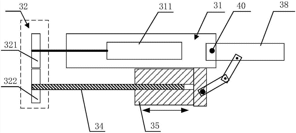
[0038] like Figure 1 to Figure 5 As shown in the figure, it is a schematic diagram of the principle of the double-layer folding back-driven finger mechanism according to the embodiment of the present invention. The double-layer folding-back driving finger mechanism according to the embodiment of the present invention includes a finger frame, a gear transmission group, a motor, a screw rod, and a screw matched with the screw rod. Nut and finger body. The gear transmission group includes a first gear and a second gear that mesh with each other, and the finger body and the finger frame are rotatably connected through a first rotating shaft.

[0039] The motor 311 is fixed in the finger frame 31 and is connected with the first gear 321 of the gear transmission group 32 through the output shaft. In practical applications, since the rotational speed output by the motor 311 may be different from the actual required rotational speed, a deceleration component may also be included to ...

Embodiment 2

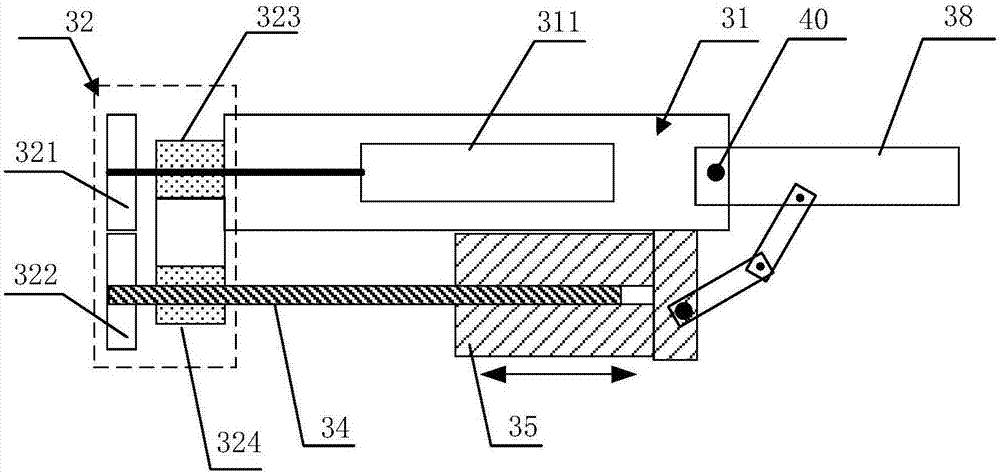
[0049] Compared with the first embodiment, the present embodiment provides an alternative solution to the implementation manner in which the nut 35 is fixed relative to the finger rack 31 in the radial direction in the first embodiment. The fact that the nut 35 is fixed relative to the finger frame 31 in the radial direction means that the nut 35 is restrained in the radial direction and released in the axial direction, and when the screw 34 is rotated, the nut 35 can move in the radial direction. The lower part of the finger frame 31 is provided with a sliding guide rail, and the nut 35 is connected with the finger frame 31 through the sliding guide rail, so that the nut 35 is fixedly connected with the finger frame 31 in the radial direction and can slide in the axial direction. The sliding guide rail may also not have a bearing function, but only provide a restraining effect in the radial direction. Preferably, the nut 35 is clamped on the sliding guide rail, so that the sli...

Embodiment 3

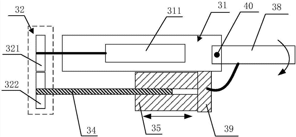
[0051] like Figure 6 to Figure 11 As shown, it is a schematic diagram of the principle of the finger mechanism driven by the double-layer folding back according to the third embodiment. The difference between this embodiment and the second embodiment is that the finger body of this embodiment includes a base phalanx and a proximal phalanx, and correspondingly, the driving manner of the nut is also different.

[0052] The above-mentioned base phalanx 42 is rotatably connected to the finger frame 31 through the first rotating shaft 40, and the base phalanx 42 and the proximal phalanx 43 are rotatably connected through the second rotating shaft 44, and are arranged between the proximal phalanx 43 and the finger frame 31. There is a first pull rod 45, one end of the first pull rod 45 is rotatably connected to the finger frame 31 through a third rotating shaft 46, and the other end of the first pull rod 45 is rotatably connected to the proximal knuckle 43 through a fourth rotating...


PUM


Abstract

The embodiment of the invention provides a double-layer turn-back driving finger mechanism. A finger body and a finger rack are rotatably connected through a first rotating shaft; a motor is connected with a first gear; a screw and a nut are arranged on the lower portion of the finger rack, the screw is connected with a second gear, and the nut is arranged on the lower portion of the finger body, connected with the finger body through a flexible connecting part or a bendable connecting part and used for driving the finger body to rotate relative to the finger rack through moving of the nut in the axial direction; and a resetting mechanism is arranged in the connecting position of the finger body and the finger rack. According to the double-layer turn-back driving finger mechanism, a double-layer turn-back transmission structure is adopted, and the special design of the screw and the nut is matched, so that original output of a power source and driving output to the finger body are located on the two layers correspondingly, and accordingly the space occupied by axial transmission output is saved.

Description

technical field [0001] The embodiments of the present invention relate to a finger mechanism, and in particular, to a finger mechanism driven by double-layer folding. Background technique [0002] The manipulator can imitate some action functions of the human hand and arm, and is an automatic operation device used to grab, carry objects or operate tools according to a fixed program. The manipulator can replace the heavy labor of humans to realize the mechanization and automation of production, and can operate in harmful environments to protect personal safety, so it is widely used in various departments of industrial production. In addition, many manipulators are also designed for disabled people to act as prosthetics for disabled people, so that disabled people have a certain ability to grasp objects. In the mechanism of the manipulator, the arm or the finger needs to be driven by the driving mechanism, so that the arm or the finger can rotate along the joint, so as to rea...

Claims


Application Information

Patent Timeline
IPC IPC(8): B25J15/00B25J15/02
CPCB25J15/0009B25J15/0213B25J15/0246
Inventor 白劲实
Owner ZORPIA ROBOT CO LTD
Why Eureka
Try Eureka