
Tensioning device for belt conveyor

A belt conveyor and tensioning device technology, applied in conveyors, transportation and packaging, etc., can solve the problems of expensive frequency converters, high maintenance costs, inability to transport materials, etc., and achieve wide practicability, reliable performance, and structure. compact effect

Inactive Publication Date: 2019-03-05
CHINA UNIV OF MINING & TECH
View PDF5 Cites 0 Cited by
  • Summary
  • Abstract
  • Description
  • Claims
  • Application Information

AI Technical Summary

Problems solved by technology

In addition, due to the need to move the tail without stopping the machine, it is required to maintain a certain tension on the tape when unloading the tape, otherwise the tape will slip and cannot transport materials
[0003] The existing mechanical and hydraulic tensioning devices for the above two working conditions cannot meet the requirements, and the frequency conversion tensioning technology can meet the requirements, but the frequency converter is expensive and the maintenance cost is high, which cannot meet the needs of ordinary users

Method used


Image

  • Tensioning device for belt conveyor

Examples


Embodiment Construction

[0023] The present invention will be further described below in conjunction with the accompanying drawings.

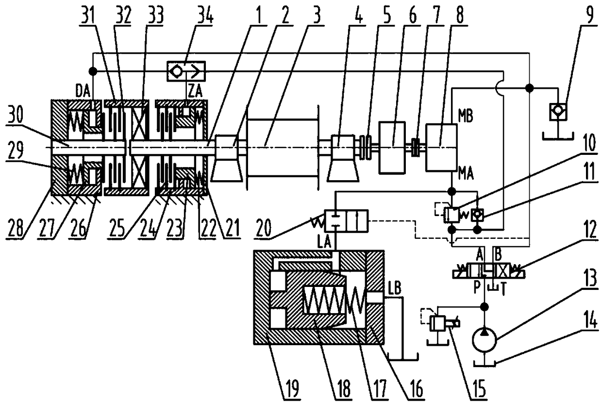
[0024] Such as figure 1 As shown, the tensioning device of the present invention is mainly composed of a reel 3, a reducer 6, a hydraulic motor 8, a brake spring 22, a brake piston 23, a brake housing 24, a brake friction plate group 25, a one-way brake housing 26, a single One-way brake piston 27, one-way brake spring 29, one-way bearing sleeve 31, one-way brake friction plate group 32, one-way bearing 33, hydraulic pump 13 and so on. in:

[0025] The reel 3 is installed on the reel shaft 1, and is located between the left bearing seat 2 and the right bearing seat 4;

[0026] The part of the drum shaft 1 protruding from the left bearing seat 2 forms a dynamic connection with the inner friction plate of the brake friction plate group 25 through the spline, and the outer friction plate of the brake friction plate group 25 is connected with the left side of the inner h...


PUM


Abstract

The invention provides a tension device for a belt conveyor. A brake and a unidirectional brake are coupled with a reel shaft, and the brake has the effect of braking; when pressure oil is not introduced, under the effect of the unidirectional brake, a reel can only unidirectionally rotate; and when the pressure oil is introduced, reverse rotation can be realized. During the start-up of the belt conveyor, torque for winding a rope can be maintained always by a hydraulic motor, so that when a rubber belt elastically extends, the rope can be wound in time to tension the rubber belt. When the rope needs to be released, the brake and the unidirectional brake are opened at the same time, the reel rotates reversely, return oil of the hydraulic motor flows back to an oil tank through a flow valve; when the pull force of the rubber belt is excessively large, and the reel is driven to rapidly rotate, the flow valve has the function that an open area can be automatically reduced, and the rotating speed of the reel is reduced; and when the pull force of the rubber belt is further increased, the flow valve is closed, a sequence valve is opened by the return oil of the hydraulic motor, and the oil flows back to the oil tank through the sequence valve. Through the adoption of the tension device provided by the invention, the demand for long-distance tensioning of the telescopic belt conveyor during start-up and the demand for the tension of the rubber belt during belt release can be met; and the tension device has the advantages of being compact in structure, reliable in properties, low in construction cost, and wide in range of practical application.

Description

technical field [0001] The invention relates to the technical field of belt conveyor tensioning, in particular to a tensioning device for a belt conveyor. Background technique [0002] The telescopic belt conveyor is used for tunneling, tunneling and tunneling in underground coal mines. When used for tunneling and tunneling, the transportation distance is relatively long. At present, the maximum length in China is 12 kilometers. Due to the length of the tape, although it is pre-tensioned before starting, the tape still has a large amount of elastic elongation during the starting process. If this part of the elastic elongation cannot be absorbed in time, the tension of the tape will decrease and the starting process cannot be completed. . Due to the limited stroke of the oil cylinder, it is impossible to fully absorb this part of the elongation. Therefore, it is necessary to tighten the winch to perform the rope winding action in time to tighten the tape and maintain the ten...

Claims


Application Information

Patent Timeline
Patent Type & Authority Patents(China)
IPC IPC(8): B65G23/44
CPCB65G23/44
Inventor 孟庆睿田祖织赵呈昊
Owner CHINA UNIV OF MINING & TECH
Learn More