
Internal blowing mechanism for steel pipe

A technology for steel pipes and air intake pipes, applied in coating, metal material coating process, hot-dip plating process, etc., can solve the problems of poor internal blowing effect, and achieve the effect of good blowing effect and expanding blowing range.

Active Publication Date: 2017-08-18
江苏泰汇不锈钢有限公司
View PDF5 Cites 0 Cited by
  • Summary
  • Abstract
  • Description
  • Claims
  • Application Information

AI Technical Summary

Problems solved by technology

[0002] For anti-corrosion, a zinc layer is often coated on the surface of the steel pipe. Inside the galvanized steel pipe, there is a galvanizing solution and a small amount of accumulated zinc slag, and these remaining zinc solutions need to be removed. The application number is CN201420803535. 8 discloses an internal blowing device for removing galvanized residual liquid on steel pipes, including a base on which three automatic internal blowing mechanisms are provided. The air inlet, the inner blowing head connected to the inner blowpipe, the front guide part and the rear guide part arranged on the base to cooperate with the inner blowpipe, and the inner blowpipe arranged on the base to drive the inner blowpipe to slide axially The driving part of the machine only blows air through one inner blowing pipe, and its inner blowing effect is poor

Method used


Image

  • Internal blowing mechanism for steel pipe
  • Internal blowing mechanism for steel pipe

Examples


Embodiment

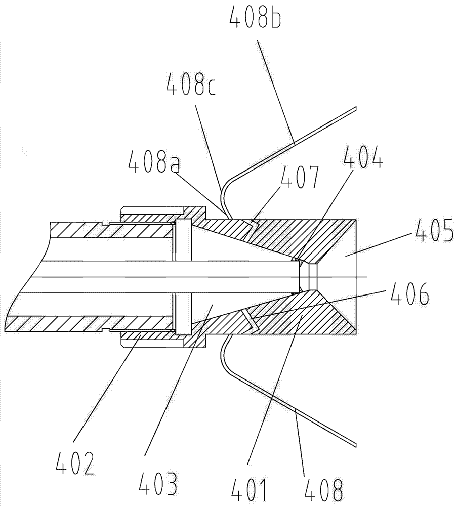
[0014] Example: such as Figure 1-Figure 2 As shown, the internal blowing mechanism for steel pipes includes a mounting base, a first air intake cavity on the mounting base, a second air intake cavity, an external blowpipe 2, and an internal blowpipe 3 disposed in the external blowpipe 2 , the first air inlet located on the first air inlet cavity on the outer blowpipe 2, the second air inlet located in the first air inlet chamber on the inner blowpipe, The third air inlet located in the second air inlet cavity on the outer blowpipe is located between the outer blowpipe and the inner blowpipe and is located between the first air inlet pipe and the third air inlet. The sealing ring between them, the inner blowing head 4 connected with the outer blowpipe 2, the front guide part 5 and the rear guide part 6 which are arranged on the base 1 and cooperate with the outer blowpipe 2 and arranged on the base 1 A driving part 7 that drives the outer blowpipe 2 to slide axially.

[0015...


PUM


Abstract

The invention discloses an internal blowing mechanism for a steel pipe. The internal blowing mechanism for the steel pipe comprises a mounting base, a first air inlet cavity, a second air inlet cavity, an external blowing pipe, an internal blowing pipe, a first air inlet, a second air inlet, a third air inlet, a sealing ring, an internal blowing head, a front guide part, a rear guide part and a driving part, wherein the first air inlet cavity and the second air inlet cavity are formed in the mounting base, the external blowing pipe is arranged on the mounting base, the internal blowing pipe is arranged in the external blowing pipe, the first air inlet is formed in the position, located on the first air inlet cavity, on the external blowing pipe, the second air inlet is formed in the position, located in the first air inlet cavity, on the internal blowing pipe, the third air inlet is formed in the position, located in the second air inlet cavity, on the external blowing pipe, the sealing ring is arranged on the position, located between the first air inlet and the third air inlet, between the external blowing pipe and the internal blowing pipe, the internal blowing head is connected to the external blowing pipe, the front guide part and the rear guide part are arranged on the base and are matched with the external blowing pipe, and the driving part is arranged on the base and drives the external blowing pipe to axially slide. According to the internal blowing mechanism for the steel pipe, air can be blown inside and outside the internal blowing pipe, the air blowing range can be expanded, and the air blowing effect is good.

Description

technical field [0001] The invention relates to the field of galvanizing steel pipes, and more specifically relates to an internal blowing mechanism for steel pipes. Background technique [0002] For anti-corrosion, a zinc layer is often coated on the surface of the steel pipe. Inside the galvanized steel pipe, there is a galvanizing solution and a small amount of accumulated zinc slag, and these remaining zinc solutions need to be removed. The application number is CN201420803535. 8 discloses an internal blowing device for removing galvanized residual liquid on steel pipes, including a base on which three automatic internal blowing mechanisms are provided. The air inlet, the inner blowing head connected to the inner blowpipe, the front guide part and the rear guide part arranged on the base to cooperate with the inner blowpipe, and the inner blowpipe arranged on the base to drive the inner blowpipe to slide axially The driving part of the machine only blows air through an ...

Claims


Application Information

Patent Timeline
IPC IPC(8): C23C2/06C23C2/18
CPCC23C2/003C23C2/06C23C2/185
Inventor 朱兴水
Owner 江苏泰汇不锈钢有限公司
Learn More