Eureka AIR delivers breakthrough ideas for toughest innovation challenges, trusted by R&D personnel around the world.

Multifunctional road CT comprehensive inspection vehicle

A comprehensive detection and multi-functional technology, applied in the direction of roads, roads, road repair, etc., can solve the problems of no effective detection method for road hidden damage, inability to detect at the same time, low detection efficiency, etc., to achieve high accuracy and contrast. Good, improve the effect of safety

Active Publication Date: 2017-08-18
重庆亲禾智千科技有限公司
View PDF5 Cites 12 Cited by
  • Summary
  • Abstract
  • Description
  • Claims
  • Application Information

AI Technical Summary

Problems solved by technology

At present, the detection and evaluation of pavement damage is mainly through manual visual inspection, which has problems such as low detection efficiency and low precision.
The current digital image detection method has the problems of low automatic detection success rate and inability to detect simultaneously with other indicators
In the process of road construction quality inspection, the detection of layer thickness and other indicators is mostly based on random sampling of drilling holes and indoor analysis and processing according to the inspection regulations. Such detection methods are highly random and not representative.
[0004] An important problem in the current road comprehensive inspection process is that a single device can detect road damage, rutting, smoothness, cracks, and friction coefficient, but there is no effective detection method for the hidden damage existing in the road. If a multi-functional equipment for simultaneous detection of road surface and subsurface diseases can be realized, it will surely raise road construction and maintenance to a new standard

Method used


Image

  • Multifunctional road CT comprehensive inspection vehicle
  • Multifunctional road CT comprehensive inspection vehicle
  • Multifunctional road CT comprehensive inspection vehicle

Examples


Embodiment Construction

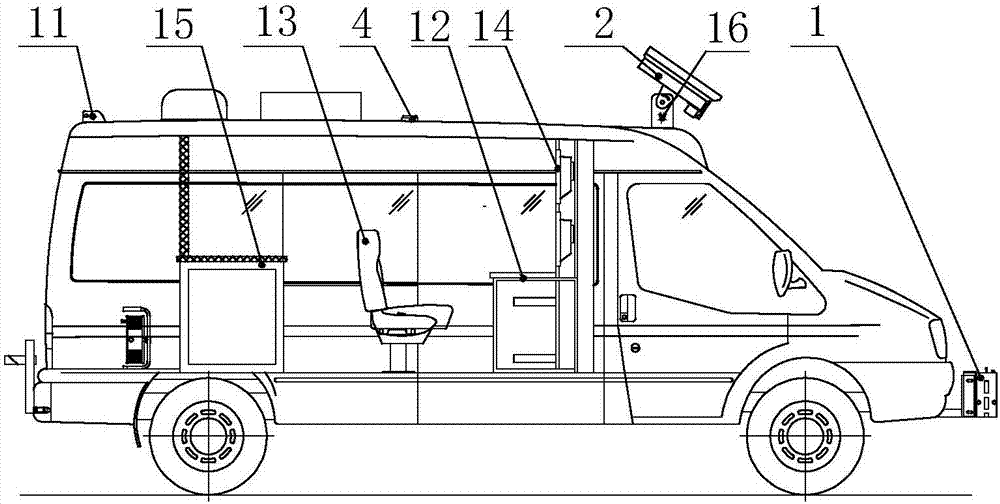
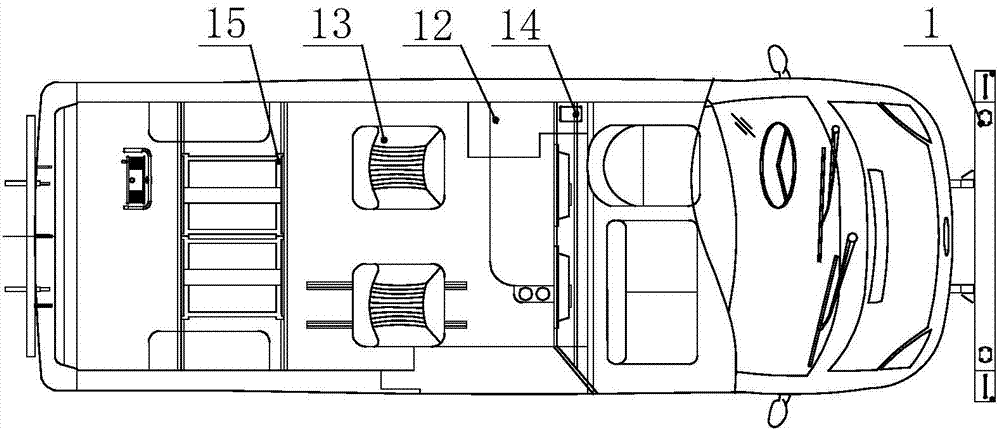
[0038] combine Figure 1-13 The multifunctional comprehensive road CT inspection vehicle shown includes a vehicle body and a detection system mounted on the vehicle body. The vehicle body is preferably a commercial vehicle type, such as Ford Transit and JAC Refine. The detection system of the present invention can be provided with an independent battery power supply, but in order to improve the continuity and stability of the detection, it is preferably powered by the power supply system carried by the car body. The compartment of the car body is equipped with an operation platform matching the detection system, and the staff can directly operate the detection system of the present invention through the operation platform. Of course, the detection system of the present invention can also be wirelessly communicated with the detection center station, and the detection system can be controlled at the remote end. The detection system implements the control.

[0039] Such as figu...


PUM


Abstract

The invention relates to the field of road detection equipment and provides a multifunctional road CT comprehensive inspection vehicle. A road CT comprehensive inspection system which integrates road surface visual inspection, laser inspection, ground penetrating radar inspection, illuminance inspection and friction coefficient inspection can be built. According to the technical scheme, the multifunctional road CT comprehensive inspection vehicle comprises a vehicle body and the inspection system carried on the vehicle body. The inspection system comprises a multifunctional laser profiler on the lower portion of the front end of the vehicle body, a road surface damage inspection camera on the upper portion of the front end of the vehicle body, a ground penetrating radar on the lower portion of the rear end of the vehicle body, a friction coefficient test device at the rear end of the vehicle body, a GPS antenna and an illuminance sensor which are arranged on the top of the vehicle body, and a rotary encoder disposed on the vehicle body. The road surface damage inspection camera inclines downwards to the front portion of the vehicle body. By means of the vehicle, nondestructive, efficient and continuous inspection can be achieved.

Description

technical field [0001] The invention relates to the field of road detection equipment, in particular to a multifunctional road CT comprehensive detection vehicle which can be used to detect and evaluate multiple road technical indicators. Background technique [0002] Road traffic plays an important role in the national economy and people's lives. In recent decades, roads have developed rapidly in countries all over the world. In the process of road construction, operation, and maintenance, multiple comprehensive detection indicators of the road are very important for the road construction department, operation department, and maintenance department. With the increase of high-grade roads and the extension of service time, road maintenance has become a core issue. How to detect and evaluate multiple indicators of roads has always been the focus of the relevant departments. [0003] Pavement inspection and maintenance work is a central link, because the pavement directly bear...

Claims


Application Information

Patent Timeline
Patent Type & Authority Applications(China)
IPC IPC(8): E01C23/01
CPCE01C23/01
Inventor 吕刚傅鹏阎旭张荣华林元江崔坤荣袁杨宇
Owner 重庆亲禾智千科技有限公司
Why Eureka
Eureka Blog
Learn More