Rotary loading machine

A technology of loader and slewing mechanism, which is applied in the direction of earth mover/excavator, mechanically driven excavator/dredger, construction, etc., which can solve the problem of affecting the progress and efficiency of loading operations, the narrow space of the working site, and the joint working mechanism Rotation and other problems, to achieve the effect of increasing the environmental adaptability of loading operations, small turning space, and saving manufacturing costs

Inactive Publication Date: 2017-08-18
SHANDONG MINGDE GANGCHENG MACHINERY CO LTD
View PDF6 Cites 3 Cited by
  • Summary
  • Abstract
  • Description
  • Claims
  • Application Information

AI Technical Summary

Problems solved by technology

However, the existing loaders cannot be rotated or the cab and the working mechanism are rotated together. When the materials to be loaded are located on both sides of the loader, it is necessary to provide a large enough rotation due to the steering of the whole machine or the rotation of the cab together with the working mechanism. When working in areas such as tunnels, field ridges and narrow spaces, the space of the work site is small, and the steering will be restricted, which will affect the progress and efficiency of loading operations.

Method used


Image

  • Rotary loading machine
  • Rotary loading machine

Examples


Embodiment 1

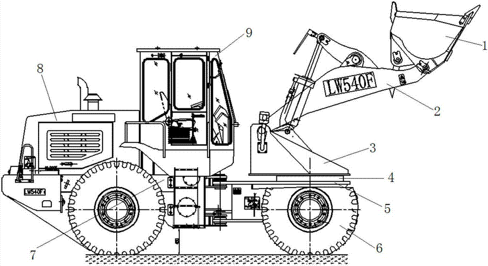
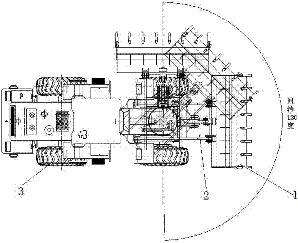
[0037] Such as figure 1 and figure 2 As shown, the present invention provides a kind of slewing loader, comprising: working mechanism, slewing mechanism 4, chassis mechanism, power mechanism 8 and driver's cab 9; It includes a hydraulic lifting arm 2 with a loading bucket 1 at the front end and a slewing bracket 3, the hydraulic lifting arm 2 is set on the slewing bracket 3, the chassis mechanism includes a loader front frame 5, and the slewing mechanism 4 is located at Between the slewing bracket 3 and the front frame 5 of the loader, the slewing mechanism 4 drives the working mechanism to turn left and right during work, and the driver's cab 9 is set independently and does not rotate with the slewing mechanism 4. The turning mechanism 4 drives the working mechanism to turn left and right by a maximum of 90 degrees, and the turning mechanism 4 includes a driving motor, and the driving motor is a hydraulic motor. The power mechanism 8 includes a diesel engine. The chassis ...

Embodiment 2

[0039] The present invention provides a slewing loader, comprising: a working mechanism, a slewing mechanism 4, a chassis mechanism, a power mechanism 8 and a cab 9; the working mechanism is located at the front of the cab 9, and the working mechanism includes a front end There is a hydraulic lifting arm 2 and a slewing bracket 3 of a loading bucket 1, the hydraulic lifting arm 2 is arranged on the slewing bracket 3, the chassis mechanism includes a loader front frame 5, and the slewing mechanism 4 is located on the slewing frame Between the bracket 3 and the front frame 5 of the loader, the slewing mechanism 4 drives the working mechanism to turn left and right during work, and the cab 9 is set independently and does not rotate with the slewing mechanism 4. The slewing mechanism 4 The working mechanism is driven to rotate at a maximum of 90 degrees left and right respectively, and the turning mechanism 4 includes a driving motor, and the driving motor is an electric motor. Th...


PUM


Abstract

The invention discloses a rotary loading machine. The rotary loading machine comprises a working mechanism, a rotary mechanism, an underpan mechanism, a power mechanism and a driving cab. The working mechanism is located on the front portion of the driving cab and comprises a hydraulic ascending-and-descending arm and a rotary support, wherein the front end of the hydraulic ascending-and-descending arm is provided with a loading hopper. The hydraulic ascending-and-descending arm is arranged on the rotary support. The underpan mechanism comprises a loading machine front frame. The rotary mechanism is located between the rotary support and the loading machine front frame. In the working process, the working mechanism is driven by the rotary mechanism to rotate leftwards and rightwards. The driving cab is arranged independently and does not rotate along with the rotary mechanism. When the rotary loading machine needs to turn the direction for loading operation, the working mechanism can rotate independently, so that the space for rotation is small, steering operation is conducted more flexibly, and furthermore, loading operation efficiency is improved; and multiple types of work tasks such as sundries clearing, soil leveling and obstacle removal can be completed by the rotary loading machine rapidly.

Description

technical field [0001] The present invention relates to the field of loaders, more specifically, to a slewing loader. Background technique [0002] Loader is a kind of earthwork construction machinery widely used in road, railway, construction, hydropower, port, mine and other construction projects. It is mainly used for shoveling bulk materials such as soil, sand, lime, coal, etc. , hard soil, etc. for light shoveling and digging operations. In the construction of roads, especially high-grade highways, loaders are used for filling and excavation of roadbed engineering, asphalt mixture and aggregate and loading of cement concrete yards. Still can undertake pushing ground of carry soil, strickle and drawing in addition the exercise such as other machine. Because fork-lift truck has operating speed fast, efficiency tall, maneuverability good, operation is light wait for an advantage, the main machine that accordingly it makes construction of the cubic metro of earth and ston...

Claims


Application Information

Patent Timeline
Patent Type & Authority Applications(China)
IPC IPC(8): E02F3/34E02F3/358
CPCE02F3/3414E02F3/358
Inventor 何鸿举
Owner SHANDONG MINGDE GANGCHENG MACHINERY CO LTD
Why Eureka
Try Eureka