Cylinder head of an internal combustion engine with integrated exhaust manifold and cooling jacket

A technology for exhaust manifolds and cylinder heads, which is applied to cylinder heads, exhaust devices, cylinders, etc., to achieve the effect of reducing the risk of thermal overheating and high thermal conductivity

Active Publication Date: 2019-06-28
VOLKSWAGEN AG +1
View PDF5 Cites 0 Cited by
  • Summary
  • Abstract
  • Description
  • Claims
  • Application Information

AI Technical Summary

Problems solved by technology

However, this measure is subject to the disadvantage of undesired consumption

Method used


Image

  • Cylinder head of an internal combustion engine with integrated exhaust manifold and cooling jacket
  • Cylinder head of an internal combustion engine with integrated exhaust manifold and cooling jacket
  • Cylinder head of an internal combustion engine with integrated exhaust manifold and cooling jacket

Examples


Embodiment Construction

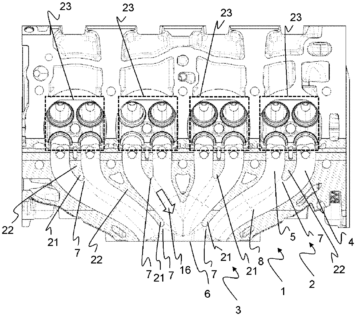
[0074] figure 1 An internal combustion engine 2 with a cylinder head 1 with an integrated exhaust manifold 3 is shown in a view from above. The exhaust manifold 3 here has eight exhaust-gas-conducting lines 4 , 5 which run from the four combustion chambers 23 in the direction of the exhaust manifold outlet 6 . Two of them, denoted here as the first line 4 and the second line 5 , lead the exhaust gas from the combustion chamber 23 to the flow connection 7 . The lines 4 , 5 are arranged approximately next to each other and are separated from each other by a common wall 22 . The lines 4 , 5 are joined (in succession) upstream of the exhaust manifold outlet 6 at a further flow connection point 7 (in the direction of flow 16 ) into a (larger) collecting line 8 , wherein the line 4 , 5 are separated from each other by the end region 21 of the wall 22 just before each flow connection point 7 .

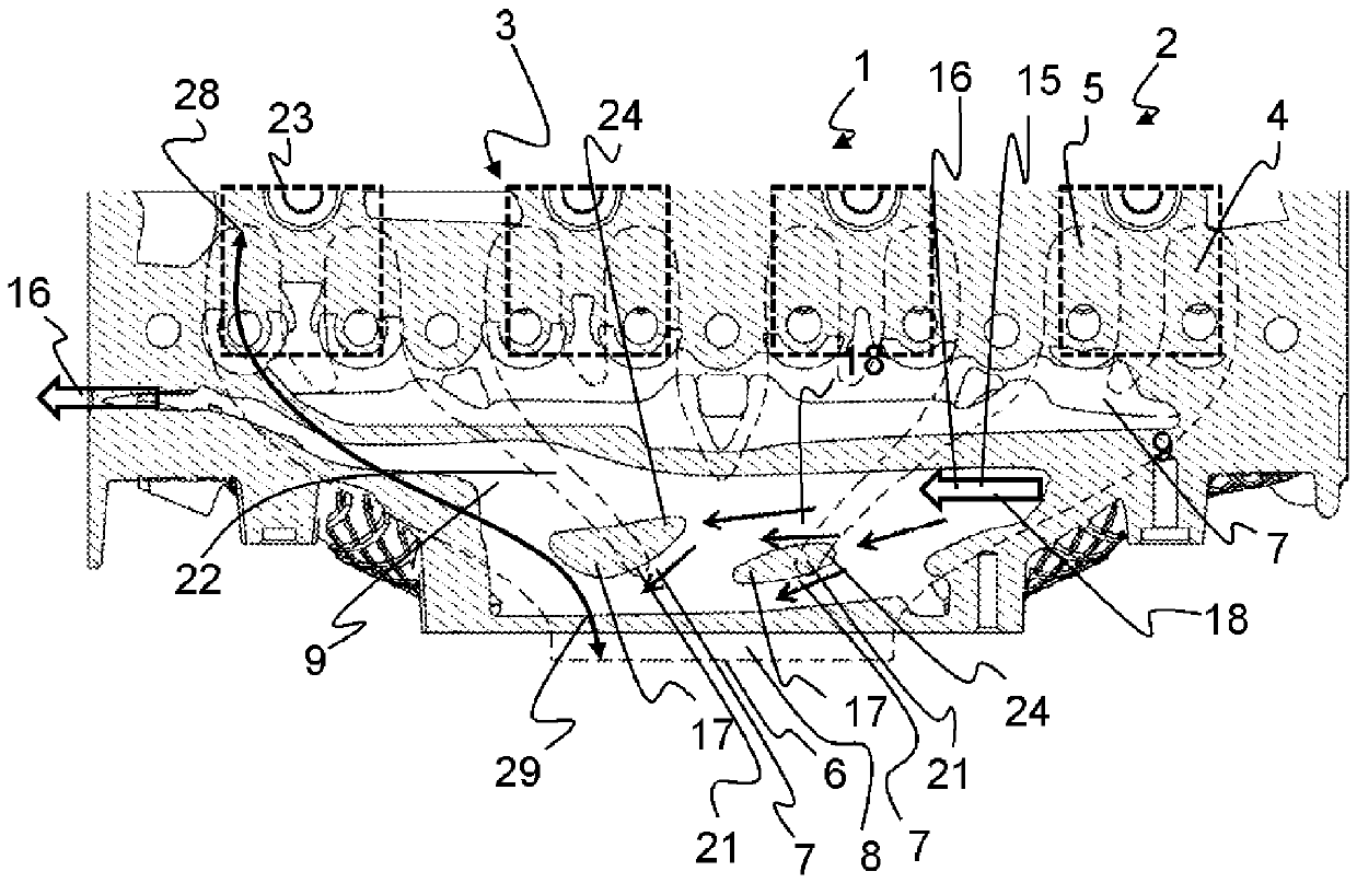
[0075] figure 2 The cylinder head 1 with integrated exhaust manifold 3 and exhaust m...


PUM


Abstract

The invention relates to a cylinder head of an internal combustion engine, with at least an integrated exhaust manifold. The exhaust manifold comprises: a, at least two conduits that direct the exhaust gas, which are arranged substantially side by side with respect to each other and are collected at the flow connection portion upstream of the exhaust manifold outlet to the manifold line, respectively, which passes through the wall Of the terminal areas are separated from each other; and b, at least one coolant jacket disposed above and / or below at least and having an upper dividing wall and a lower dividing wall, wherein the at least one coolant jacket and the pipe are separated from each other by a common dividing wall The coolant jacket is passed through the coolant in a fixed flow direction, wherein at least one tab extends between the upper dividing wall and the lower boundary wall in the coolant jacket, which has an upstream flow in the upstream; the influent flow being separated by a flow of coolant, wherein the coolant flow is accelerated downstream of the partition in a first zone of the coolant jacket, wherein the portion of the first zone or tab directly adjacent to the inflow surface is arranged directly at and / or on the mobile connection site and / or the terminal area.

Description

technical field [0001] The invention relates to a cylinder head of an internal combustion engine with an integrated exhaust manifold and cooling jacket. Such a cylinder head is produced in particular by a casting method, in which a plurality of exhaust-gas-carrying lines of the exhaust manifold and the cooling jacket are integrated in a one-piece component. The exhaust-gas-conducting line and the cooling jacket have a common boundary wall made of cast material. Background technique [0002] Such a cylinder head is used in particular as part of an internal combustion engine of a motor vehicle, for example a diesel engine, a gasoline engine or a hybrid engine. The heat released during the combustion of fuel in the combustion chamber of the internal combustion engine or motor block is emitted partly via the walls of the motor block to the cylinder head and partly via the exhaust gas flow to adjacent components and the environment place. In order to avoid thermal overloading ...

Claims


Application Information

Patent Timeline
Patent Type & Authority Patents(China)
IPC IPC(8): F02F1/40F01N13/10F01N3/02F02F1/36
CPCF02F1/40F01N13/10F02F1/243
Inventor L.亨切尔P.卡伟尔克M.施普林格S.格尔克M.拜恩A.伦佩拉J.赫拉德斯奇
Owner VOLKSWAGEN AG
Why Eureka
Try Eureka