
Crystal current sensor based on composite optical vortex

A technology of crystal current and composite light, applied in voltage/current isolation, optics, instruments, etc., can solve the problem of reducing the sensitivity of fiber optic current transformers, and achieve the effects of improving measurement accuracy and accuracy, easy installation, and small footprint

Active Publication Date: 2017-08-18
SHANGHAI UNIV
View PDF5 Cites 7 Cited by
  • Summary
  • Abstract
  • Description
  • Claims
  • Application Information

AI Technical Summary

Problems solved by technology

The invention makes full use of the characteristic that the optical vortex can maintain a good circular polarization state during the transmission process, and utilizes the principle that the change of the polarization state of the light beam caused by the Faraday magneto-optic effect can be directly reflected in the compound spot, effectively solving the problem caused by linear birefringence. The problem of reducing the sensitivity of fiber optic current transformers, so as to realize the function of current sensing

Method used

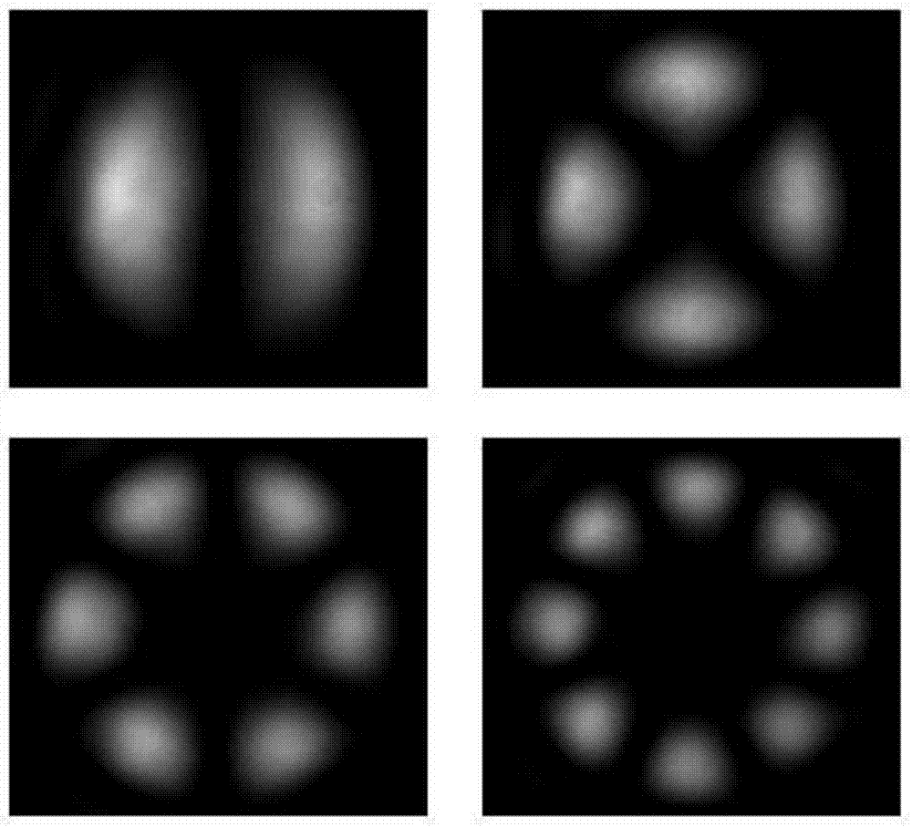
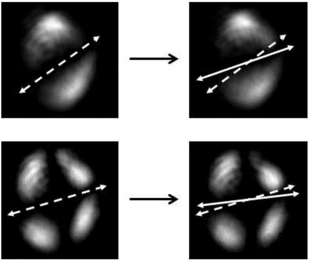

Image

  • Crystal current sensor based on composite optical vortex
  • Crystal current sensor based on composite optical vortex
  • Crystal current sensor based on composite optical vortex

Examples


Embodiment Construction

[0026] Preferred embodiments of the present invention are described in detail as follows:

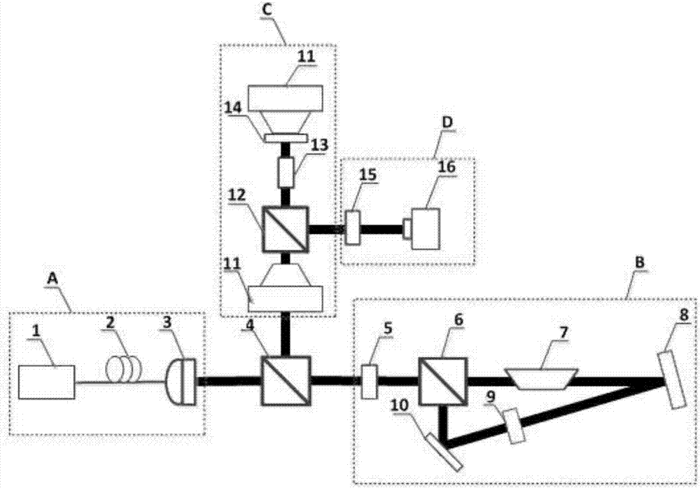
[0027] In this example, see figure 1, a crystal current sensor based on a composite optical vortex, including a laser emitting unit A, a front-end non-polarizing beam splitter 4, a composite beam generating unit B, a crystal sensing unit C and a detection unit D, and the output end of the laser emitting unit A Connect the input end of the front-end non-polarizing beam splitter 4, the input end and the output end of the composite beam generating unit B are both connected to the signal end of the front-end non-polarizing beam splitter 4, and the output end of the front-end non-polarizing beam splitter 4 is connected to the crystal sensor The input end of the unit C, the output end of the crystal sensing unit C is connected to the input end of the detection unit D; the laser emitting unit A is used to output the fundamental mode Gaussian beam of the linear polarization state, and the Gauss...


PUM


Abstract

The invention discloses a crystal current sensor based on composite optical vortex. A laser emission unit is used to emit a linear polarization state fundamental mode Gaussian beam, and a composite beam generating unit is used to divide the linear polarization state fundamental mode Gaussian beam into two beams, and is used to modulate the two beams into optical vortex beams, which are combined together, and are converted into circular polarization type composite optical vortex beams. A crystal sensing unit is used to transmit the composite optical vortex beams into a crystal along the optical axis of the crystal, and is used to apply the current to the crystal to generate a magnetic field along the direction of the optical axis of the crystal. A detection unit is used to detect the light intensity distributions of the composite optical vortex beams before and after the application of the magnetic field, and the deflection of the composite optical vortex beams occurs, and the current is calculated by calculating the deflection degree, and therefore a current sensing function is realized. The circular polarization state characteristic of the optical vortex during a transmission process is maintained, and the change of the beam polarization state by using Faraday magneto-optic effect can be directly displayed in composite spots, and therefore a problem of reduction of sensitivity of an optical fiber current sensor caused by linear birefringence is effectively solved.

Description

technical field [0001] The invention relates to a crystal current sensor, in particular to a Sagnac interferometer type crystal current sensor, which is applied to the technical fields of magnetic field measurement and current sensing. Background technique [0002] At present, the principle of most optical current transformers is based on the Faraday magneto-optic effect, which encountered a pair of contradictions in the process of practical application: on the one hand, the Verdet constant of the silica fiber is low, and in order to improve the sensitivity, the winding turns of the fiber ring need to be increased On the other hand, the increase in the number of fiber turns will additionally introduce linear birefringence, which will reduce the sensitivity of the fiber optic current transformer, and excessive linear birefringence will even inhibit the Faraday effect. [0003] Optical vortex beams can have infinitely many eigenstates, and the eigenstates are mutually orthogon...

Claims


Application Information

Patent Timeline
IPC IPC(8): G01R15/24G02B27/28
CPCG01R15/246G02B27/283G02B27/286
Inventor 王廷云喻双凤庞拂飞李先进郭强
Owner SHANGHAI UNIV
Learn More