Double-coil coupled multi-wave exploration system

A coupled, double-coil technology, applied in the field of transient electromagnetic detection, can solve the problems of not being able to take into account both the shallow detection information and the deep detection information, the power reduction of the power supply system, the loss of the shallow detection information, etc., to improve the shallow detection information. Detection effect, reducing interference, eliminating the effect of multiple magnetic field aliasing

Active Publication Date: 2017-08-18
CHONGQING CUILU DETECTION TECH CO LTD +1
View PDF5 Cites 9 Cited by
  • Summary
  • Abstract
  • Description
  • Claims
  • Application Information

AI Technical Summary

Problems solved by technology

[0004] At present, the main problems existing in domestic transient electromagnetic transmitters are: first, the delay of the magnetic field shutdown is too long, and the shallow detection information is seriously lost; second, the emission magnetic field is unstable, and the power supply

Method used


Image

  • Double-coil coupled multi-wave exploration system
  • Double-coil coupled multi-wave exploration system
  • Double-coil coupled multi-wave exploration system

Examples


Embodiment 1

[0083] Parameter settings of the main transmitter coil and the slave transmitter coil:

[0084] Both the main transmitting coil and the secondary transmitting coil adopt single-turn cross-linked polyethylene copper core power cables.

[0085] The main transmitting coil has 4 turns, and the cross-sectional area of ​​the copper core power cable is 80mm 2 , coil radius 17.5m, inductance 3mH, resistance 0.125Ω.

[0086] 1 turn from the transmitting coil, the cross-sectional area of ​​the copper core power cable is 20mm 2 , coil radius 17.5m, inductance 0.26mH, resistance 0.185Ω.

[0087] When emitting a large magnetic moment:

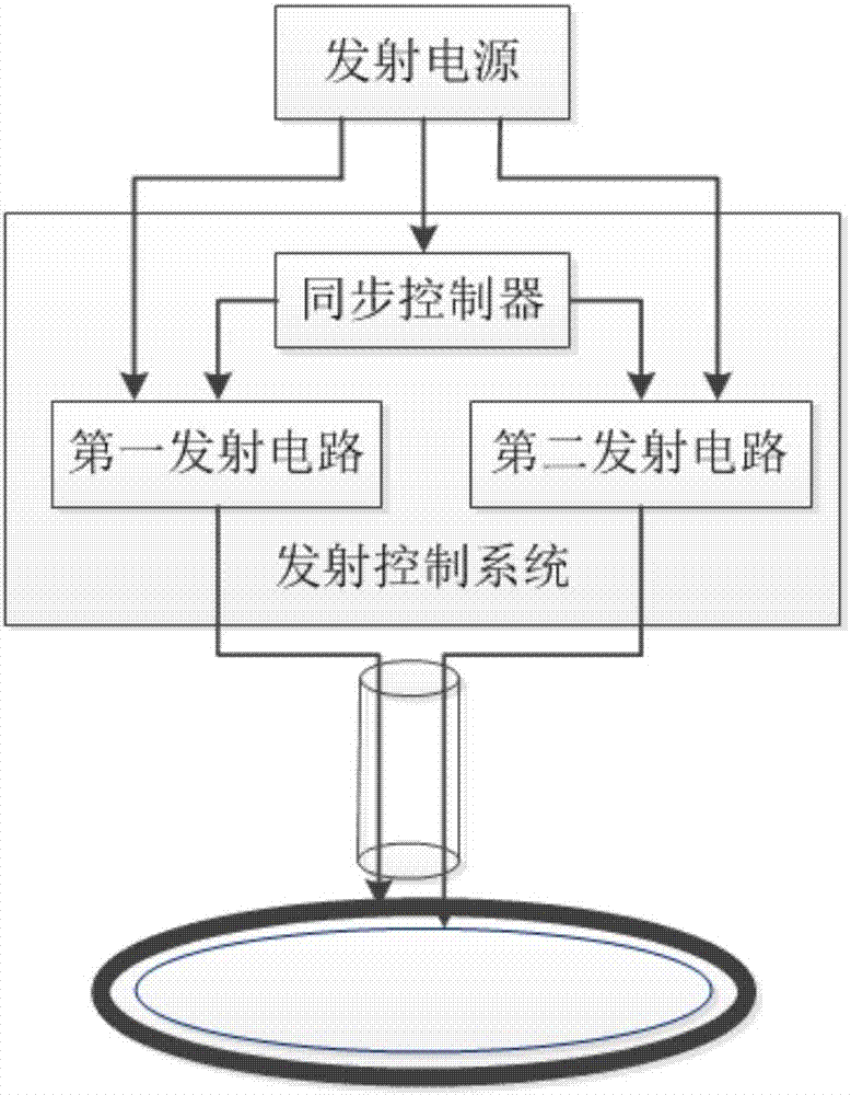
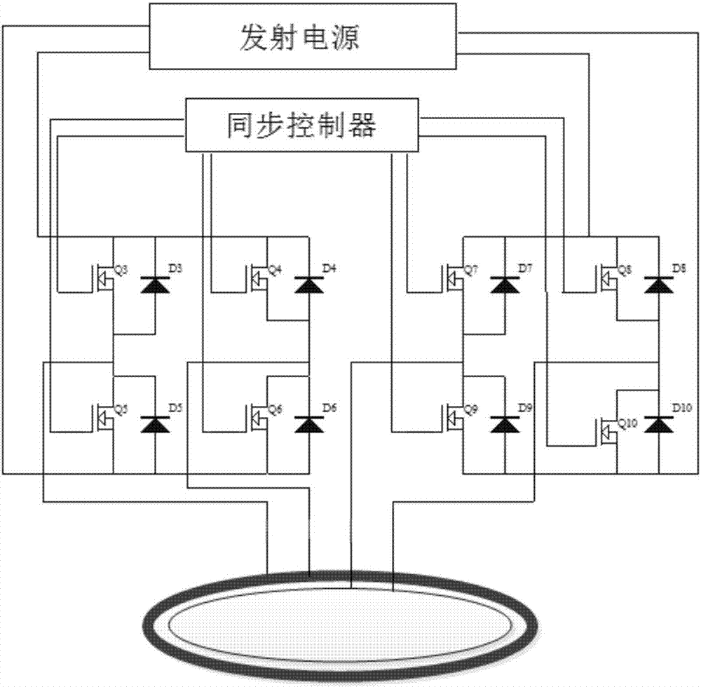
[0088] The transmission is jointly synthesized by the main transmitting coil and the secondary transmitting coil, and the pulse waveform received by the main transmitting coil and the secondary transmitting coil is a bipolar trapezoidal pulse, which rises linearly and falls linearly.

[0089] From image 3 It can be seen that the specific parameters ar...

Embodiment 2

[0107] The parameter settings of the main transmitting coil and the secondary transmitting coil are the same as those in Embodiment 1.

[0108] When emitting a large magnetic moment:

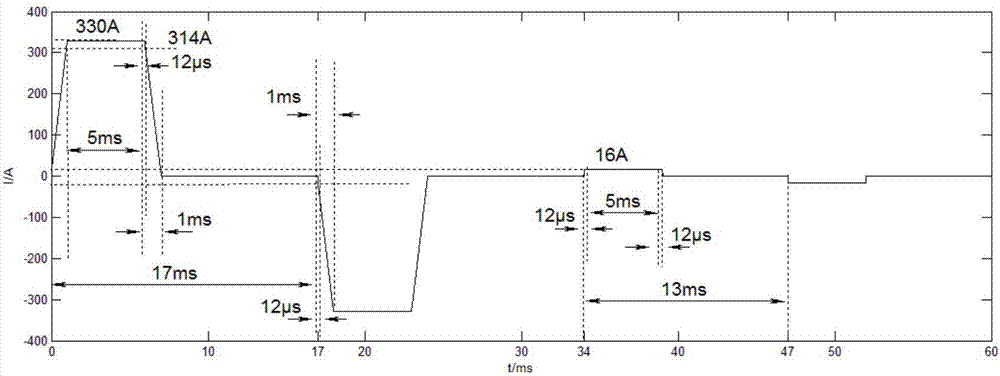
[0109]The emission is jointly synthesized by the main transmitting coil and the secondary transmitting coil, the main transmitting coil passes a bipolar trapezoidal pulse current, and the secondary transmitting coil passes a bipolar triangular wave current. Control the current from the transmitting coil to realize the constant power of the first excitation field, the compensation effect diagram is shown in Figure 5 shown.

[0110] From Figure 4 It can be seen that the specific parameters are:

[0111] Peak magnetic moment: 1300,000Am2, equivalent to 4 turns 330A.

[0112] Flat Top Ripple: 1%.

[0113] Rise time: 1ms.

[0114] Fall time: 1ms.

[0115] Flat top width: 5ms.

[0116] Large magnetic moment half wave: 17ms.

[0117] When emitting a small magnetic moment:

[0118] It is tra...


PUM

PropertyMeasurementUnit
Cross-sectional areaaaaaaaaaaa
Radiusaaaaaaaaaa
Inductanceaaaaaaaaaa

Abstract

The invention discloses a double-coil coupled multi-wave exploration system comprising a transmission control system. A first pulse signal output terminal group of the transmission control system is connected with a main transmitting coil and a second pulse signal output terminal group of the transmission control system is connected with a slave transmitting coil. The main transmitting coil and the slave transmitting coil are coupled coils and are overlapped. A receiving coil module is arranged at the edge of the main transmitting coil and the receiving coil module and the main transmitting coil are intersected partially; and the partial orthographic projection of the main transmitting coil and the partial orthographic projection of the receiving coil module are overlapped. The double-coil coupled multi-wave exploration system has the following beneficial effects: alternate detection of the deep part and the shallow part can be realized; for the shallow detection, the current turn-off time is short; the losses are low, the detection precision is high, and the work efficiency is high; the structure is simple and the mobility is high; the main transmitting coil and the receiving coil module are intersected partially and thus the mutual inductance influences between the main transmitting coil and the receiving coil are cancelled, so that the exploration precision is improved.

Description

technical field [0001] The invention relates to the technical field of transient electromagnetic detection, in particular to a double-coil coupled multi-wave survey system. Background technique [0002] Transient electromagnetic method is also called time domain electromagnetic method (TEM), which uses ungrounded return line or grounding line source to transmit a pulsed magnetic field to the ground. The method of observing the secondary eddy current field. Simply put, the basic principle of the transient electromagnetic method is the law of electromagnetic induction. The decay process is generally divided into early, middle and late stages. The early electromagnetic field is equivalent to the high-frequency component in the frequency domain, with fast attenuation and small skin depth; while the late component is equivalent to the low-frequency component in the frequency domain, with slow attenuation and large skin depth. The geoelectric characteristics at different depths...

Claims


Application Information

Patent Timeline
IPC IPC(8): G01V3/10
Inventor 付志红姜升王耀朱学贵王唯邱婧竹魏秋生李军强
Owner CHONGQING CUILU DETECTION TECH CO LTD
Why Eureka
Try Eureka