
shield conductive path

A technology of conductive paths and shielding tubes, applied in the field of shielded conductive paths, can solve problems such as manufacturing difficulties

Active Publication Date: 2020-01-14
SUMITOMO WIRING SYST LTD
View PDF6 Cites 0 Cited by
  • Summary
  • Abstract
  • Description
  • Claims
  • Application Information

AI Technical Summary

Problems solved by technology

[0004] In the above-mentioned conventional shielding conductive path, when manufacturing the electromagnetic shielding tube, the resin inner layer and the outer casing should be joined together with the metal metal layer, and relatively large equipment such as an insert molding machine is required. In addition, depending on the situation, Chemical and mechanical surface treatment has to be performed on the metal layer, etc., and there are cases where manufacturing is difficult

Method used


Image

  • shield conductive path
  • shield conductive path
  • shield conductive path

Examples


Embodiment 1

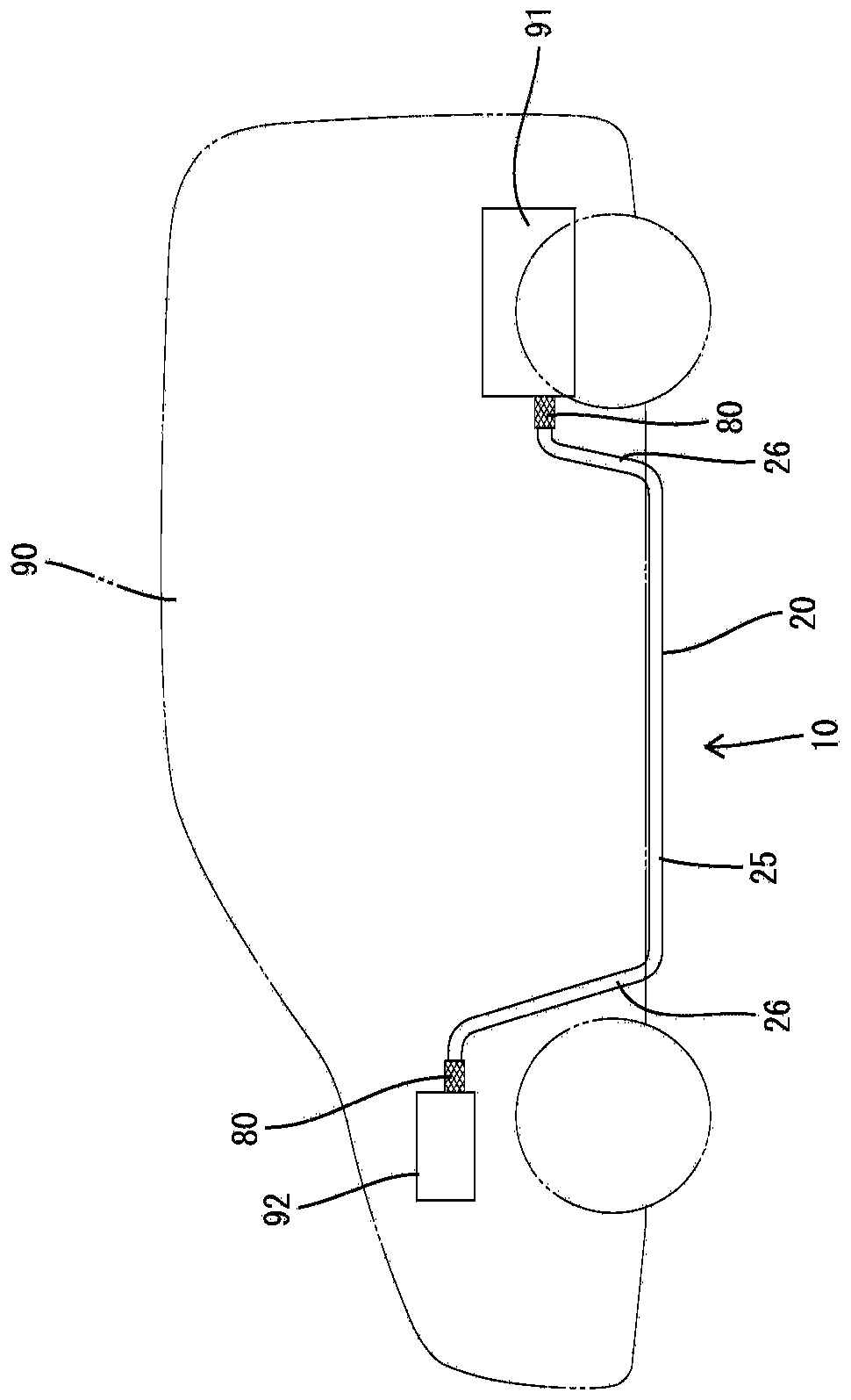
[0021] Below, refer to Figure 1 to Figure 5 Example 1 will be described. Regarding the shielded conductive path 10 of Embodiment 1, in vehicles such as hybrid cars, such as figure 1 As shown, for example, equipment 91 such as a high-voltage battery provided at the rear of the vehicle body 90 should be connected to equipment 92 such as an inverter and a fuse box provided at the front of the vehicle body 90, and wired to the chassis of the vehicle body 90. . In addition, the devices 91 and 92 are accommodated in conductive shielding cases.

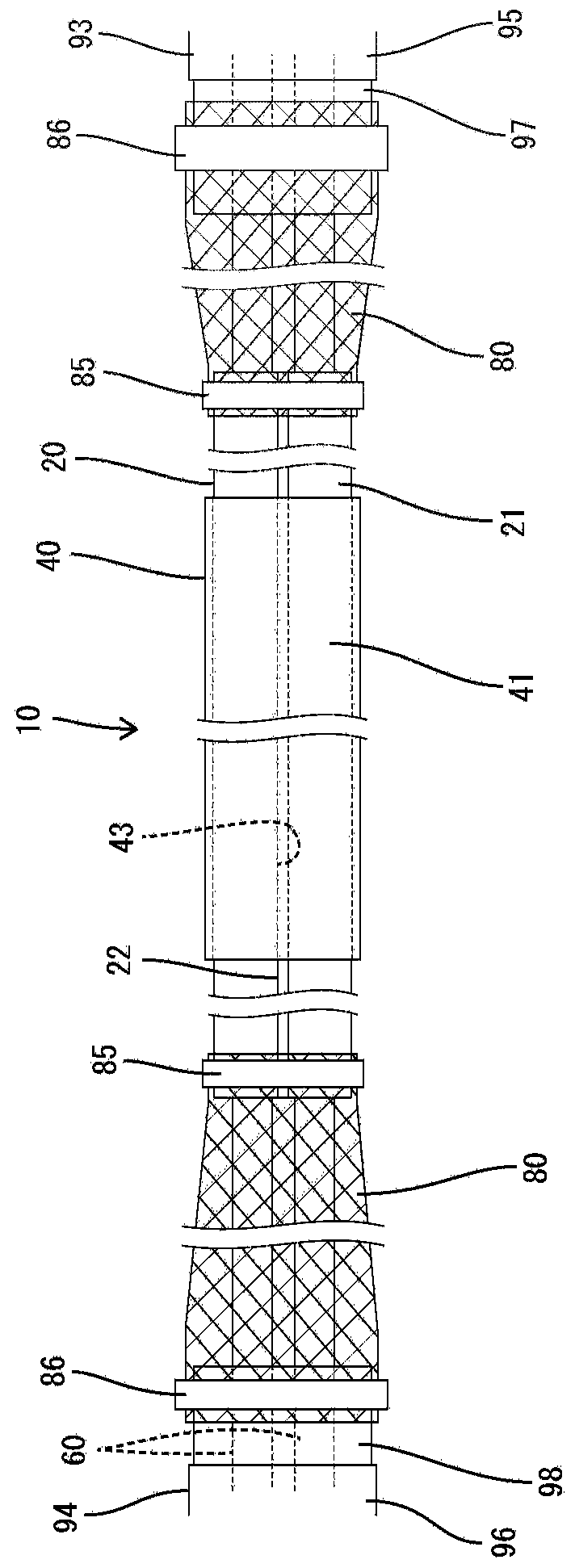
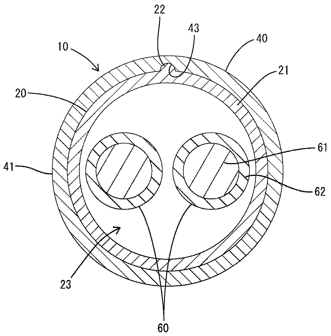
[0022] The shielded conductive path 10 has a plurality of (two in the case of Embodiment 1) electric wires 60 , a shielded tube 20 , and a resin tube 40 separate from the shielded tube 20 .

[0023] Such as image 3 As shown, the electric wire 60 is an unshielded electric wire composed of a conductor 61 (copper, aluminum, etc.) and an insulating resin coating 62 covering the periphery of the conductor 61 . Terminal fittings (not shown)...

Embodiment 2

[0045] Figure 6 ~ Figure 8 Example 2 is shown. In the shielded conductive path 10A of the second embodiment, contrary to the first embodiment, the concave portion 43A is provided on the outer peripheral surface of the shielding tube 20A, and the convex portion 22A is provided on the inner peripheral surface of the resin tube 40A. In other words, in Embodiment 1, the concave portion 43A opens inward and the convex portion 22A protrudes outward, but in the case of Embodiment 2, the concave portion 43A opens outward and the convex portion 22A protrudes inward.

[0046] The concave portion 43A and the convex portion 22A are formed to be able to fit each other, and have the same shape as that of the first embodiment. When the resin tube 40A is assembled to the shield tube 20A, the convex portion 22A of the resin tube 40A fits into the recess 43A of the shield tube 20A, and the resin tube 40A is held circumferentially positioned on the shield tube 20A. This point is also the same...


PUM


Abstract

The present invention provides a shielded conductive path that is easy to manufacture. The shielding conductive path (10) has: a cylindrical shielding tube (20) having an insertion space (23) for an electric wire (60); and a resin tube (40) externally inserted into the shielding tube (20) in a pluggable manner ), and separated from the shielding tube (20). Since the resin tube (40) has substantially no fear of peeling off of the paint during bending, it can exhibit a predetermined identification function.

Description

technical field [0001] The invention relates to a shielded conductive path with a shielding function. Background technique [0002] Conventionally, shielded conductive paths are known that include electric wires routed on a chassis of a vehicle such as a hybrid vehicle and a cylindrical shield tube through which the electric wires are inserted. At this time, the shielding tube mainly plays the role of protecting the electric wire and shielding noise. For example, Patent Document 1 discloses an electromagnetic shielding tube in which a resin inner layer, a metal metal layer, and a resin outer layer are integrally bonded. [0003] Patent Document 1: Japanese Patent Laid-Open No. 2012-165562 [0004] In the above-mentioned conventional shielding conductive path, when manufacturing the electromagnetic shielding tube, the resin inner layer and the outer casing should be joined together with the metal metal layer, and relatively large equipment such as an insert molding machine ...

Claims


Application Information

Patent Timeline
Patent Type & Authority Patents(China)
IPC IPC(8): H01B7/17H01B7/18
CPCH01B7/17H01B7/18H05K9/0098B60R16/0215H05K9/0007
Inventor 杉野秀寿
Owner SUMITOMO WIRING SYST LTD
Learn More