
Low-profile and high-efficient polarization transformation transmitting array antenna

A polarization conversion, array antenna technology, applied in the direction of antenna, antenna grounding switch structure connection, radiating element structure and other directions, can solve the problems of low aperture radiation efficiency, high longitudinal profile, low polarization conversion efficiency and aperture radiation efficiency, etc. , to achieve the effect of promoting development and application, high radiation efficiency, and high polarization conversion efficiency

Inactive Publication Date: 2017-08-18
XIAN TECHNOLOGICAL UNIV
View PDF1 Cites 16 Cited by
  • Summary
  • Abstract
  • Description
  • Claims
  • Application Information

AI Technical Summary

Problems solved by technology

The existing multi-polarized transmission array antenna uses a two-dimensional three-layer rectangular ring slot structure as the array unit, and realizes multiple polarization modes by adjusting the size of the rectangular ring slot in the orthogonal direction and the rotation angle of the feed source. The longitudinal section of this unit is relatively high, and the total thickness is more than 0.5 wavelengths at the center frequency; and the interaction of the transmission coefficient amplitude and phase of this unit in the orthogonal polarization direction is relatively large, resulting in the polarization of the transmission array antenna The conversion efficiency and the aperture radiation efficiency in each polarization mode are relatively low, and the maximum aperture radiation efficiency is only 27%
Moreover, the structure of the traditional transmission array unit is relatively complicated, and the number of layers of the dielectric plate is at least three layers, and the total thickness is at least 0.5 wavelengths at the center frequency, resulting in an excessively large longitudinal section height of the transmission array, which is not easy to integrate with the system
Although the existing transmission array antenna technology has been widely used, with the development of wireless communication technology and the increasing popularity of polarization diversity technology, the communication system urgently requires the same antenna to be able to freely switch multiple polarization modes. And it has high polarization conversion efficiency, high aperture radiation efficiency and low profile height, but it is very difficult to meet these requirements at the same time
[0003] To sum up, the problems existing in the existing technology are: the polarization mode of the traditional transmission array antenna is single, and the free switching of different polarization modes cannot be realized; The polarization conversion efficiency and aperture radiation efficiency of traditional multi-polarized transmission array antennas are relatively low
The reason why the polarization mode of the traditional transmission array antenna is single is that: the polarization mode of the traditional transmission array unit is single, and it does not have the ability to change between different polarizations; the reason for the excessive height of the longitudinal section of the traditional transmission array antenna is that: the traditional The transmission array unit adopts a two-dimensional multi-layer structure with an excessively large longitudinal section. If sufficient transmission coefficient amplitude and phase change range are to be ensured, the number of dielectric plate layers should be at least 3 layers, and the thickness should be more than 0.5 wavelengths at the center frequency. ; The reason why the polarization conversion efficiency and aperture radiation efficiency of the traditional multi-polarized transmission array antenna is relatively low is that the transmission loss of the three-layer rectangular ring slot unit is relatively large, and the amplitude phase of the unit in the orthogonal polarization direction The interaction effect is relatively large
[0004] The difficulty in solving existing technical problems lies in the fact that it is difficult for traditional transmission array antennas to simultaneously possess many advantages such as the ability to switch between multiple polarization modes, high polarization conversion efficiency, high aperture radiation efficiency, and low profile height.

Method used


Image

  • Low-profile and high-efficient polarization transformation transmitting array antenna
  • Low-profile and high-efficient polarization transformation transmitting array antenna
  • Low-profile and high-efficient polarization transformation transmitting array antenna

Examples


Embodiment Construction

[0031] In order to make the object, technical solution and advantages of the present invention more clear, the present invention will be further described in detail below in conjunction with the examples. It should be understood that the specific embodiments described here are only used to explain the present invention, not to limit the present invention.

[0032] The application principle of the present invention will be described in detail below in conjunction with the accompanying drawings.

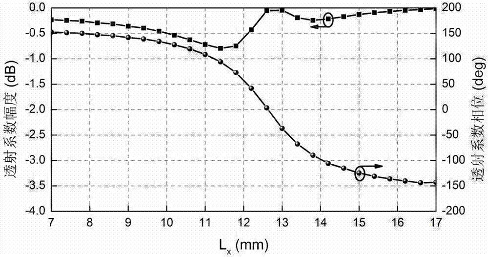
[0033] like figure 1 As shown, the low-profile high-efficiency polarization-converting transmissive array antenna provided by the embodiment of the present invention includes: a feed source 1 and a transmissive array unit 2 .

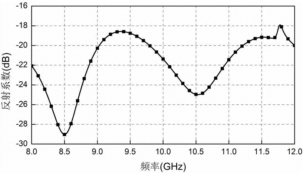
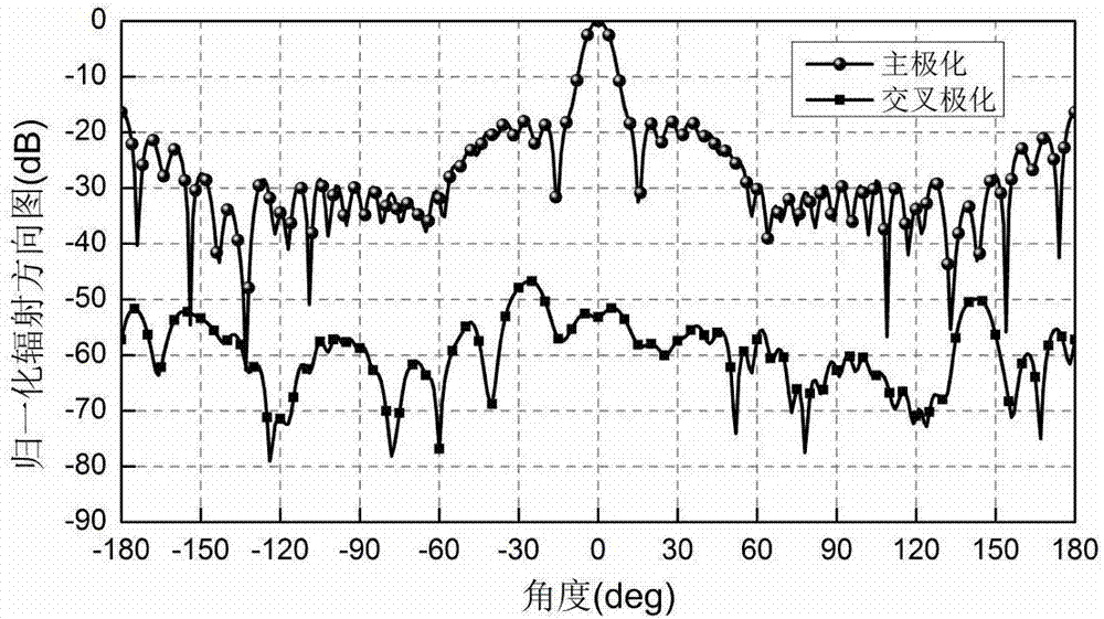
[0034] The pyramid horn antenna is used as the feed source 1 of the transmission array antenna, and the three-dimensional cross oscillator with a double-layer structure is used as the transmission array unit 2 . The transmission array unit 2 is formed by perio...


PUM


Abstract

The invention belongs to the field of planar transmitting array antennas, and discloses a low-profile and high-efficient polarization transformation transmitting array antenna. The low-profile and high-efficient polarization transformation transmitting array antenna comprises: a pyramidal horn antenna used as a feed of the transmitting array antenna, and double-layer and three-dimensional portion symmetrical cross oscillators of different sizes used as transmitting array cells. The double-layer and three-dimensional portion symmetrical cross units proposed by the invention have the capability of transforming among multiple polarization modes and small transmission loss. The transmitting array antenna formed by the proposed three-dimensional portion symmetrical cross oscillator units overcomes the shortage of a single polarization mode of the conventional transmitting array antenna, and can realize various polarization modes (including linear polarization and circular polarization). The aperture using efficiency of the antenna in various polarization modes is up to 54% or more, and the longitudinal section height thereof is also reduced significantly compared with that of the conventional transmitting array antenna, so that the development and application of the transmitting array antenna technology are effectively promoted.

Description

technical field [0001] The invention belongs to the technical field of planar transmission array antennas, in particular to a low-profile high-efficiency polarization conversion transmission array antenna. Background technique [0002] The planar transmission array antenna is a new type of high-gain antenna formed by combining the advantages of the traditional curved lens antenna and the microstrip array antenna. It is composed of a planar transmission array and a feed antenna. The planar transmissive array is composed of transmissive frequency-selective surface units with similar topological structures. By performing phase compensation on each unit on the array, the required radiation beam can be generated on the other side of the array. Because of its small size, light weight, simple structure, low production cost, high gain and many other advantages, it has been widely used in wireless communication systems. Traditional transmissive array antennas usually use a multi-lay...

Claims


Application Information

Patent Timeline
Patent Type & Authority Applications(China)
IPC IPC(8): H01Q15/02H01Q15/24H01Q1/36H01Q1/50
CPCH01Q15/02H01Q1/36H01Q1/50H01Q15/24
Inventor 钟显江齐华雷志勇任安虎董绵绵陈红张勇程光伟
Owner XIAN TECHNOLOGICAL UNIV
Learn More