Terminal crimping machine

A terminal crimping machine and crimping die technology, applied in the direction of connection, vehicle connector, electrical components, etc., can solve the problems of reducing work efficiency, time-consuming, complicated operation, etc., to achieve automatic control, reduce energy consumption, reasonable The effect of configuration

Active Publication Date: 2017-08-18
JIANGSU BOZHIWANG AUTOMATION EQUIP CO LTD
View PDF4 Cites 1 Cited by
  • Summary
  • Abstract
  • Description
  • Claims
  • Application Information

AI Technical Summary

Problems solved by technology

[0003] At present, the terminal crimping machine is only equipped with one set of crimping dies. When using the same crimping machine for multiple terminal crimping operations, it is necessary to replace the crimping dies. Therefore, there is an urgent need for a terminal crimping machine that can automatically replace the crimping die

Method used


Image

  • Terminal crimping machine
  • Terminal crimping machine
  • Terminal crimping machine

Examples


Embodiment 1

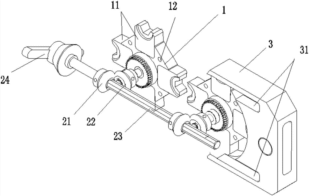
[0037] Such as image 3 As shown, the conversion assembly 2 includes a sector-shaped driving wheel 21 and a sector-shaped driven wheel 22. Two sets of sector-shaped driven wheels 22 are respectively arranged at the center of the main bodies of two groups of crimping modules 1, and two sets of sector-shaped driving wheels 21 are fixedly connected to the synchronous shaft 23 respectively. The rotation of two sets of fan-shaped driving wheels 21 is driven by rotating the synchronous shaft 23, and the fan-shaped driving wheels 21 drive the rotation of the fan-shaped driven wheels 22 which are engaged with it, and then respectively drive the center of the crimping module 1 fixedly connected with the fan-shaped driven wheels 22 shaft, with the rotation of the central shaft, the two groups of crimping modules 1 realize synchronous rotation, and then realize the synchronous replacement of crimping dies.

Embodiment 2

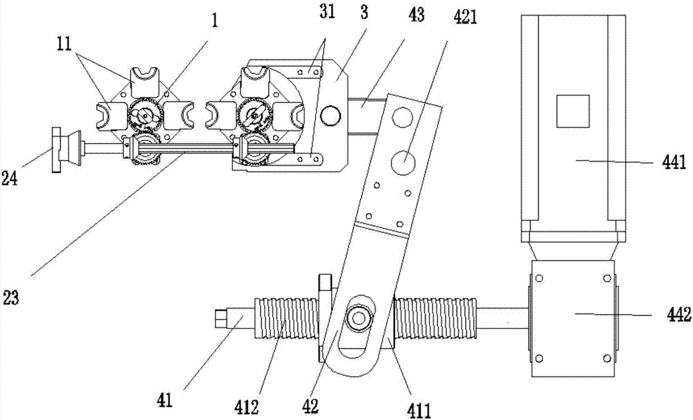
[0039] Such as Figure 4 As shown, the central axis of the crimping module 1 is connected with the first gear and the second gear meshed with it. The difference from Embodiment 1 is that the sector driven wheel 22 is connected with the central axis of the second gear, and the second gear drives the second gear. The rotation of the first gear can increase the positioning accuracy of the crimping die by increasing the number of teeth of the first gear, and the arrangement of multi-stage gears has higher working reliability, longer service life and stable transmission ratio.

[0040] figure 2 , image 3 and Figure 4 Among them, the reference numeral 11 represents crimping dies of different specifications set according to requirements.

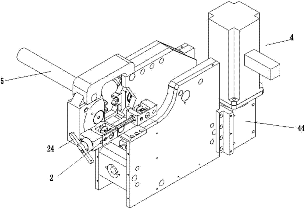
[0041]When working, put the cable 5 to be processed into the processing station, provide power to the crimping module 1 through the power assembly 4, and perform the crimping operation. When the crimping size or crimping shape of the cable 5 ...


PUM


Abstract

The invention discloses a terminal crimping machine. The terminal crimping machine comprises two groups of crimping modules used for crimping and two groups of converting components used for mould replacement; at least two crimping moulds are uniformly arranged at the peripheral outside of each crimping module main body, and the crimping modules of the two groups of the crimping modules are arranged in one-to-one correspondence; the converting components are connected with the central shafts of the two groups of the crimping modules respectively; through the converting components, the crimping modules are rotated to realize replacement of the crimping moulds; each converting component comprises a fan-shaped drive wheel and a fan-shaped driven wheel; the two groups of the fan-shaped driven wheels are arranged at the central shafts of the crimping module main body respectively; the two groups of the fan-shaped drive wheels are fixedly connected with a synchronous shaft respectively; and through rotation of the synchronous shaft, the two groups of the crimping modules rotate synchronously to realize synchronous replacement of the crimping moulds. By adoption of the technical scheme, synchronous replacement of the crimping moulds can be realized, automatic control can be realized, the replacement operating steps of the crimping moulds can be simplified, and the work efficiency can be increased.

Description

technical field [0001] The invention relates to the field of machinery, in particular to a terminal crimping machine. Background technique [0002] The terminal crimping machine is a necessary tool for continuous crimping of wires in the power industry in line capital construction and line maintenance. With the rise of electric vehicles, there are more and more electric vehicle charging stations, and charging stations cannot do without charging pile cables, and the necessary tool for continuous crimping of wires is a terminal crimping machine. [0003] At present, the terminal crimping machine is only equipped with one set of crimping dies. When using the same crimping machine for multiple terminal crimping operations, it is necessary to replace the crimping dies. Therefore, there is an urgent need for a terminal crimping machine capable of automatically replacing crimping dies. [0004] In view of the above-mentioned defects existing in the existing terminal crimping mach...

Claims


Application Information

Patent Timeline
Patent Type & Authority Applications(China)
IPC IPC(8): H01R43/048
CPCH01R43/048H01R2201/26Y02E60/10
Inventor 司向良
Owner JIANGSU BOZHIWANG AUTOMATION EQUIP CO LTD
Why Eureka
Try Eureka