Power transmission joint defense inspection system

A connecting rod and left-walking technology, applied in the direction of electrical components, cable installation, overhead line/cable equipment, etc., can solve the problems of poor work reliability, falling down, etc. fall effect

Inactive Publication Date: 2017-08-18
STATE GRID CORP OF CHINA +2
View PDF9 Cites 4 Cited by
  • Summary
  • Abstract
  • Description
  • Claims
  • Application Information

AI Technical Summary

Problems solved by technology

However, when it is necessary to climb a slope, it is easy to back off, and in severe cases, it may even fall off the overhead line, and the work reliability is poor.

Method used


Image

  • Power transmission joint defense inspection system
  • Power transmission joint defense inspection system
  • Power transmission joint defense inspection system

Examples


Embodiment 1

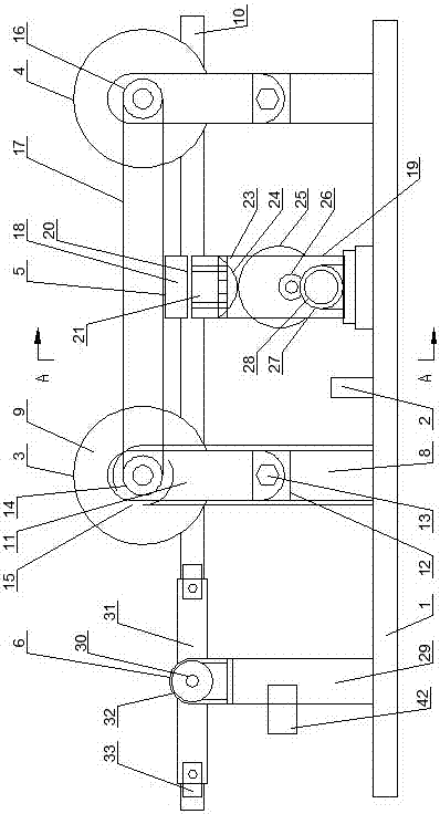
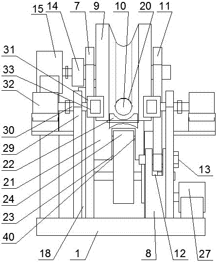
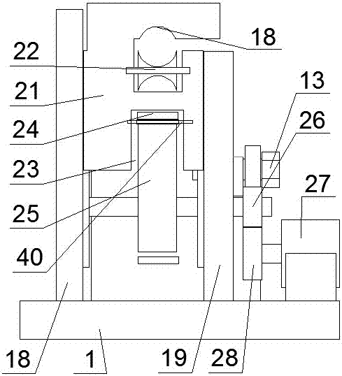
[0031] like figure 1 , figure 2 and image 3 As shown, a power transmission joint prevention and inspection system includes a base 1, a programmable controller 2 arranged on the base 1 and a camera 42 connected to the programmable controller, and a left walking mechanism with the same structure is set on the base 1 3 and the right traveling mechanism 4, a locking and deicing mechanism 5 is provided between the left traveling mechanism 3 and the right traveling mechanism 4, and a foreign matter handling mechanism 6 is arranged on the left side of the left traveling mechanism 3;

[0032]The left traveling mechanism 3 and the right traveling mechanism 4 all include a rear vertical board 7 and a front vertical board 8 oppositely arranged on the base 1, the height of the front vertical board 8 is lower than that of the rear vertical board 7, the upper end of the rear vertical plate 7 is provided with a walking wheel 9 through a rotating shaft, and the walking wheel 9 is pressed ...

Embodiment 2

[0045] The difference from Embodiment 1 is that anti-slip layers are provided in the upper arc-shaped groove 20 and the groove 22 of the wire wheel.

Embodiment 3

[0047] like figure 1 , figure 2 and image 3 As shown, a power transmission joint prevention and inspection system includes a base 1 . The programmable controller 2 and the camera connected with the programmable controller are arranged on the base 1, the left traveling mechanism 3 and the right traveling mechanism 4 with the same structure are arranged on the described base 1, and the left traveling mechanism 3 and the A locking and deicing mechanism 5 is arranged between the right traveling mechanism 4, and a foreign body processing mechanism 6 is arranged on the left side of the left traveling mechanism 3;

[0048] The left traveling mechanism 3 and the right traveling mechanism 4 all include a rear vertical board 7 and a front vertical board 8 oppositely arranged on the base 1, the height of the front vertical board 8 is lower than that of the rear vertical board 7, the upper end of the rear vertical plate 7 is provided with a walking wheel 9 through a rotating shaft, a...


PUM


Abstract

The invention discloses a power transmission joint defense inspection system which comprises a base, a programmable controller set on the base, and a camera connected with the programmable controller. A left walking mechanism and a right walking mechanism of the same structure are arranged on the base. A locking and de-icing mechanism is arranged between the left walking mechanism and the right walking mechanism. A foreign body disposing mechanism is arranged at the left side of the left walking mechanism. The condition of transmission lines can be observed, and foreign body disposal is efficient and effective.

Description

technical field [0001] The invention belongs to the technical field of power transmission line inspection systems, and in particular relates to a power transmission joint defense inspection system. Background technique [0002] Foreign objects (advertising strips, balloons, etc.) are easily entangled on the wires of transmission lines, and damage caused by lightning strikes, external breakages, fires and other events in the wire shelves are the most common defects in the operation and maintenance of overhead transmission lines. The middle and high altitude parts are very harmful. It is difficult for the operator to find or eliminate the above defects without entering the wire. There is a great limit to the operation of entering the wire with live work, which is often restricted by the safety clearance of live work and cannot be carried out. Dangerous, especially the operation of entering broken strands or equipotential removal of foreign objects has great safety risks and is...

Claims


Application Information

Patent Timeline
IPC IPC(8): H02G1/02H02G7/16
CPCH02G1/02H02G7/16
Inventor 杨留生邝石程生安赵明李宏伟高峰严燕
Owner STATE GRID CORP OF CHINA
Why Eureka
Try Eureka