Stacked Bend Piezo Actuator

A piezoelectric ceramic, piezoelectric ceramic sheet technology, applied in the direction of generator/motor, piezoelectric effect/electrostrictive or magnetostrictive motor, electrical components, etc., to achieve extended application range, strong overall structure, enhanced The effect of large mechanical displacement output

Active Publication Date: 2019-03-29
HARBIN INST OF TECH
View PDF6 Cites 0 Cited by
  • Summary
  • Abstract
  • Description
  • Claims
  • Application Information

AI Technical Summary

Problems solved by technology

[0004] Most of the current multilayer piezoelectric ceramic actuators are longitudinally stretchable and deformable drivers, that is, when an excitation electrical signal is applied, the entire actuator will produce stretching deformation along the thickness direction of the piezoelectric ceramic sheet, and the multilayer piezoelectric ceramics that can produce bending deformation as a whole Drive, there is no organization or company to design and develop at present, and bending deformation is an actuation method often used in the design of piezoelectric actuators, so a bending multilayer piezoelectric ceramic actuator is designed as the basis of piezoelectric actuators Components will have a profound impact on expanding the application range of piezoelectric elements and promoting the development of piezoelectric drive technology

Method used


Image

  • Stacked Bend Piezo Actuator
  • Stacked Bend Piezo Actuator
  • Stacked Bend Piezo Actuator

Examples


specific Embodiment approach 1

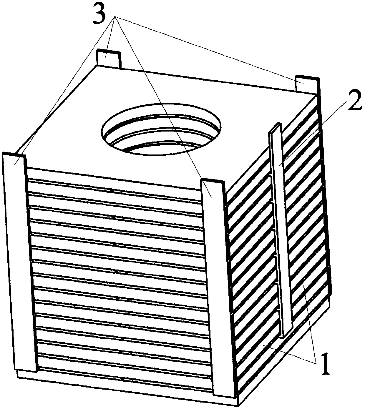
[0026] Specific implementation mode one: combine Figure 1 to Figure 7 Describe this embodiment in detail. The stacked curved piezoelectric ceramic driver described in this embodiment includes n layers of piezoelectric ceramic sheets 1, ground electrodes 2 and excitation electrodes 3, wherein n is an even number greater than or equal to 2; In a specific embodiment, n is set to 16.

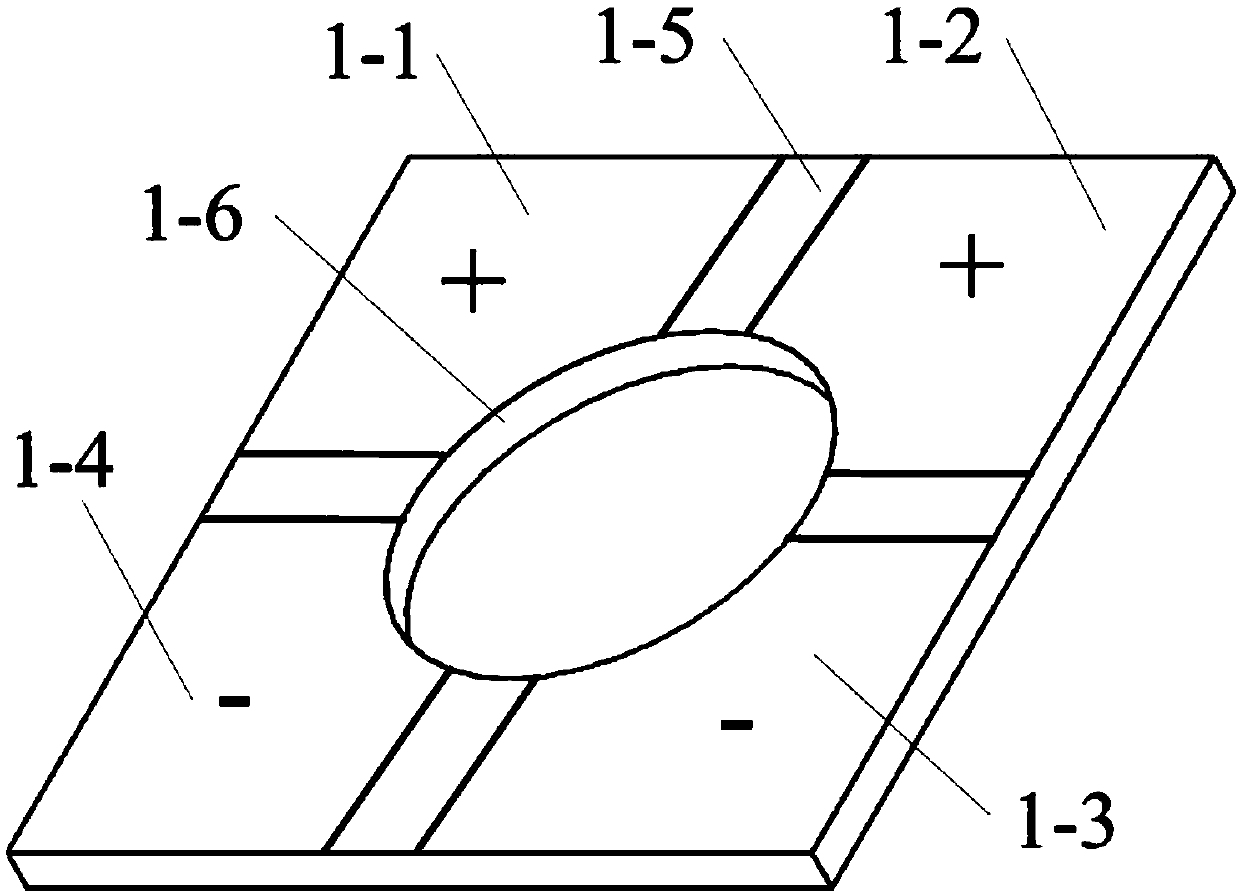
[0027] The piezoelectric ceramic sheet 1 adopts a sheet structure so that it can obtain a larger displacement output at a lower excitation voltage; the shape of the piezoelectric ceramic sheet 1 can be circular or regular m-gon, wherein m is greater than or equal to An even number of 4, wherein in this specific embodiment, the shape of the piezoelectric ceramic sheet 1 is specifically set to a square; the central position of the piezoelectric ceramic sheet 1 can be provided with a central hole 1-6, and the cross-sectional shape of the central hole 1-6 can be set It is a circle or a regular p-gon, ...

specific Embodiment approach 2

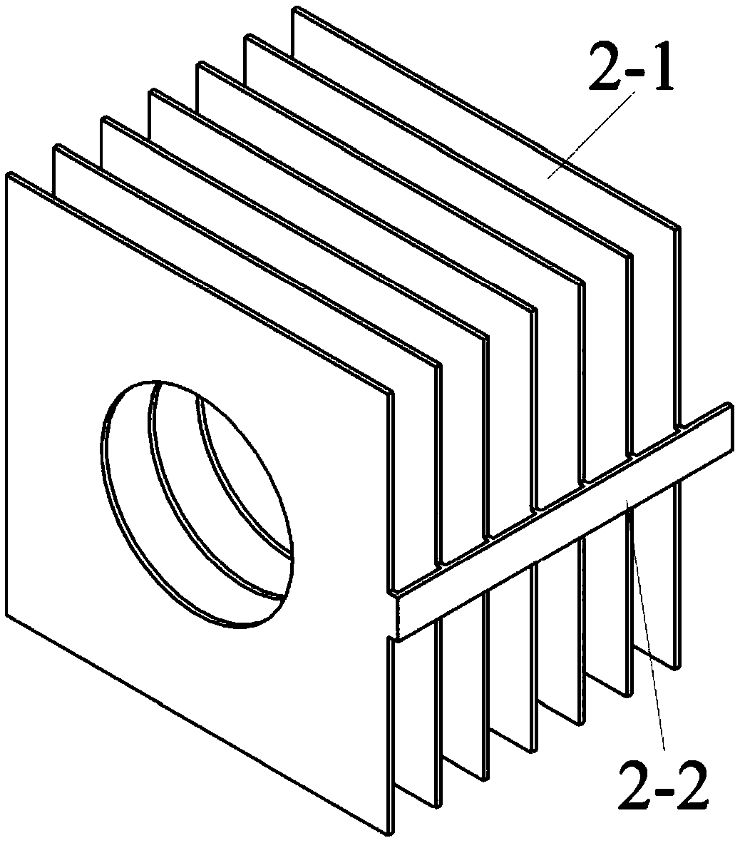
[0030] Specific implementation mode two: combination Figure 8Describe this embodiment in detail. This embodiment is a further description of the laminated curved piezoelectric ceramic driver described in Embodiment 1. In this embodiment, the first pole of the piezoelectric ceramic sheet 1 with multiple layers The excitation extraction electrodes 3-2 corresponding to the polarized region 1-1, the second polarized region 1-2, the third polarized region 1-3 and the fourth polarized region 1-4 are connected together as an excitation group A. It applies the excitation electric signal, and the ground electrode sheet 2-1 of the ground electrode 2 is connected to the common end of the excitation electric signal through the ground lead-out electrode 2-2 to realize the grounding of the piezoelectric ceramic sheet 1. Due to the different polarization directions, the first polarization area 1 Part of the piezoelectric ceramic sheet corresponding to -1 and the second polarization region 1...

specific Embodiment approach 3

[0031] Specific implementation mode three: combination Figure 9 Describe this embodiment in detail. This embodiment is a further description of the laminated curved piezoelectric ceramic driver described in Embodiment 1. In this embodiment, the first pole of the piezoelectric ceramic sheet 1 with multiple layers The excitation extraction electrode 3-2 corresponding to the polarization region 1-1 and the excitation extraction electrode 3-2 corresponding to the third polarization region 1-3 are connected together as an excitation group A, and the excitation group A corresponding to the second polarization region 1-2 The excitation extraction electrode 3-2 of the excitation extraction electrode 3-2 corresponding to the fourth polarization zone 1-4 is connected together as the excitation group B, and the excitation electric signal is applied to the excitation group A, and the ground electrode sheet 2-2 of the ground electrode 2 1 The piezoelectric ceramic sheet 1 is grounded by c...


PUM


Abstract

The invention discloses a laminated bending-type piezoelectric ceramic driver and belongs to the technical field of piezoelectric driving. The laminated bending-type piezoelectric ceramic driver is used for enriching the current variety of piezoelectric elements and extending the application scope of the piezoelectric elements. Piezoelectric ceramic sheets of the laminated bending-type piezoelectric ceramic driver are divided evenly into four independent polarized sectors. A ground electrode includes ground electrode sheets and a ground extraction electrode; and an excitation electrode includes excitation electrode sheets and excitation extraction electrodes. Both the ground electrode and the excitation electrode are in a comb-teeth-shaped configuration. According to the invention, excitation is carried out by using a piezoelectric ceramic d33 mode and adopting a four-divided-polarized-sector configuration form of the piezoelectric ceramic sheets, so that a bending deformation in a certain direction or in an orthogonal direction of two spaces can be achieved by the laminated bending-type piezoelectric ceramic driver. The ground electrode and the excitation electrode which are in a comb-teeth-shaped configuration are adopted and it can be effectively guaranteed that the multi-layer piezoelectric ceramic sheets are connected mechanically in series and electrically in parallel; the laminated bending-type piezoelectric ceramic driver has a good overall structure; and the laminated bending-type piezoelectric ceramic driver serves as a supplement to the existing piezoelectric elements, and the application scope of the piezoelectric elements will be extended and the development of the piezoelectric driving technical field will be advanced.

Description

technical field [0001] The invention relates to a piezoelectric ceramic driver and belongs to the technical field of piezoelectric driving. Background technique [0002] As a new type of precision drive and micro-positioning technology, piezoelectric drive mainly uses the inverse piezoelectric effect of piezoelectric materials to convert electrical energy into mechanical energy. Due to its unique structural design, flexible design, no electromagnetic interference and no Features such as electromagnetic interference, millisecond-level fast response, and power-off self-locking have attracted widespread attention in recent years, and have been successfully applied in precision optical instruments, biomedical equipment, aerospace and other technical fields. [0003] Piezoelectric ceramics are one of the most important components in piezoelectric actuators, and play a key role in the process of converting electrical energy input into mechanical energy output. In order to obtain ...

Claims


Application Information

Patent Timeline
Patent Type & Authority Patents(China)
IPC IPC(8): H02N2/04H02N2/06
CPCH02N2/04H02N2/062
Inventor 刘英想王良石胜君刘军考冯培连
Owner HARBIN INST OF TECH
Why Eureka
Try Eureka