
Grounding grid reinforcing steel bar bending device

A bending device and grounding grid technology, applied in the field of machinery and equipment, can solve the problems of grounding grid corrosion, time-consuming and laborious, galvanized layer damage, etc., to reduce labor intensity, reduce safety hazards, and ensure the effect of bending quality

Inactive Publication Date: 2017-08-22
STATE GRID CHONGQING ELECTRIC POWER
View PDF7 Cites 3 Cited by
  • Summary
  • Abstract
  • Description
  • Claims
  • Application Information

AI Technical Summary

Problems solved by technology

[0002] During the long-term operation of high-voltage transmission lines, the safety function of the grounding grid cannot be ignored. When laying the grounding grid, the steel bars on the surface of the grounding grid should be bent. Since there is no bending tool specially used for the grounding grid steel bars in the power system, All parts that need to be bent are formed by manual bending, sledgehammer knocking or oxygen welding and baking; the efficiency of manual bending and oxygen welding and baking is very low, time-consuming and laborious; Under external operating conditions, it is easy to corrode and break the grounding grid in a short period of time, affecting the safe operation of the line, and it is easy to injure people, posing safety hazards; in addition, although there are electric steel bars in the construction industry Bending machines, but due to the limitations of the place of use, these steel bending machines are difficult to apply to the power system

Method used


Image

  • Grounding grid reinforcing steel bar bending device
  • Grounding grid reinforcing steel bar bending device
  • Grounding grid reinforcing steel bar bending device

Examples


Embodiment 1

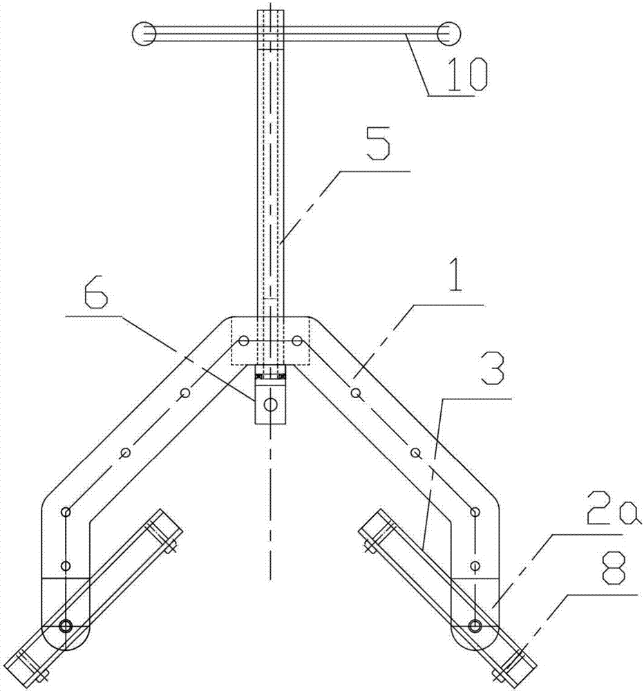
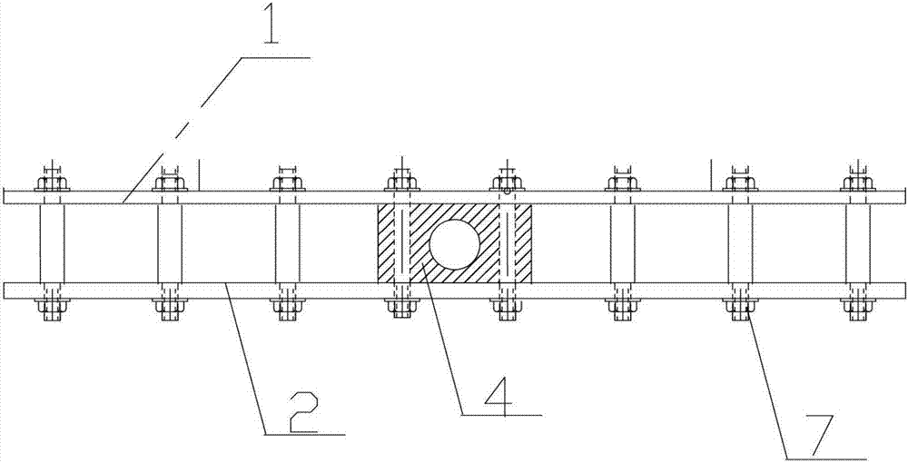
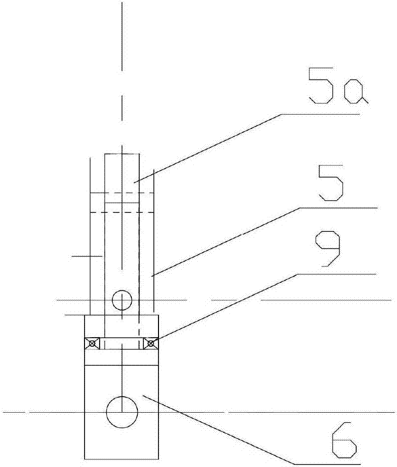
[0015] Example 1, such as Figure 1-3 Shown: the grounding grid steel bar bender of the present invention is made of front fixed plate 1, rear fixed plate 2, steel bar rotating channel steel 3, screw seat 4, leading screw 5, steel bar fixed frame 6, front and rear fixed plate bolts 7, steel bar Locking bolt 8, bearing 9, leading screw handle 10 are formed.

[0016] Both the front fixing plate 1 and the rear fixing plate 2 include a top connecting arm, a left support arm and a right support arm. The two ends of the arm, the length of the left support arm and the right support arm of the rear fixed plate 2 are greater than the left support arm and the right support arm length of the front fixed plate 1, and the left support arm of the rear fixed plate 2 and the right support arm bottom bend downward Folded into a vertical bent portion 2a, the bottom of the front fixing plate 1 is also bent downwards, but the length of the bent portion bent downwards is less than the length of t...


PUM


Abstract

The invention discloses a grounding grid reinforcing steel bar bending device. A front fixing plate and a back fixing plate each comprise a top connecting arm, a left support arm and a right support arm, each left support arm and the corresponding right support arm are distributed in a splayed manner, and the upper end of each left support arm and the upper end of the corresponding right support arm are connected to the two ends of the corresponding top connecting arm correspondingly; the lengths of the left support arm and the right support arm of the back fixing plate are larger than those of the left support arm and the right support arm of the front fixing plate, the lower portions of the left support arm and the right support arm of the back fixing plate are downwards bent to form vertical bending parts, and the front fixing plate and the back fixing plate are connected through front and back fixing plate bolts; the lower portions of the vertical bending parts of the left support arm and the right support arm are hinged to reinforcing steel bar rotation box iron through rotating pins, a lead screw base is connected between the top connecting arms of the front fixing plate and the back fixing plate, and a through hole is formed in a reinforcing steel bar fixing frame; and the lower portion of the lead screw is fixedly provided with a lead screw penetrating needle which extends into the reinforcing steel bar fixing frame, and a bearing is arranged between the lead screw penetrating needle and the reinforcing steel bar fixing frame. The grounding grid reinforcing steel bar bending device is simple in structure and convenient to carry, and reinforcing steel bars can be quickly and effectively bent and machined.

Description

technical field [0001] The invention relates to a steel bar bender for a grounding grid, which belongs to the field of mechanical equipment. Background technique [0002] During the long-term operation of high-voltage transmission lines, the safety function of the grounding grid cannot be ignored. When laying the grounding grid, the steel bars on the surface of the grounding grid should be bent. Since there is no bending tool specially used for the grounding grid steel bars in the power system, All parts that need to be bent are formed by manual bending, sledgehammer knocking or oxygen welding and baking; the efficiency of manual bending and oxygen welding and baking is very low, time-consuming and laborious; Under external operating conditions, it is easy to corrode and break the grounding grid in a short period of time, affecting the safe operation of the line, and it is easy to injure people, posing safety hazards; in addition, although there are electric steel bars in th...

Claims


Application Information

Patent Timeline
Patent Type & Authority Applications(China)
IPC IPC(8): B21F1/00
CPCB21F1/002
Inventor 杜斌牟磊代泽林彭聪谭银松
Owner STATE GRID CHONGQING ELECTRIC POWER
Learn More