Method for transforming milling cutter into grooving cutter and UC grooving cutter

A technology for slotting cutters and milling cutters, which is applied in the field of methods and UC slotting cutters, and milling cutters for changing slotting cutters. It can solve the problems of discarding old milling cutters, difficult processing of slotting cutters, and cumbersome steps, and achieves easy processing and reduced processing difficulty. Small, easy-to-step effects

Inactive Publication Date: 2017-08-22
昆山伟吉电子有限公司
View PDF8 Cites 4 Cited by
  • Summary
  • Abstract
  • Description
  • Claims
  • Application Information

AI Technical Summary

Problems solved by technology

[0004] The purpose of the present invention is to propose a method for changing a milling cutter to a groove cutter, which can solve the proble...

Method used


Image

  • Method for transforming milling cutter into grooving cutter and UC grooving cutter
  • Method for transforming milling cutter into grooving cutter and UC grooving cutter
  • Method for transforming milling cutter into grooving cutter and UC grooving cutter

Examples


Embodiment Construction

[0037] In order to enable those skilled in the art to better understand the technical solution of the present invention, the technical solution of the present invention will be further described below in conjunction with the accompanying drawings and through specific implementation methods.

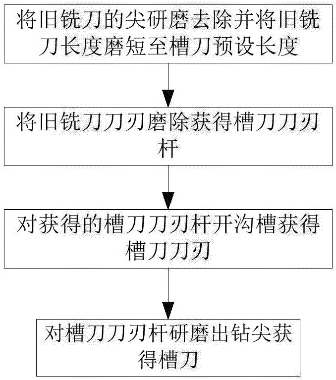
[0038] Such as figure 1 As shown, the present embodiment provides a method for changing a milling cutter to a slotting cutter. The method can change an old milling cutter into a slotting cutter through grinding, grooving and other processes, and specifically includes the following steps;

[0039] Step 1. Grinding and removing the tip of the old milling cutter and shortening the length of the old milling cutter to the preset length of the slotting cutter;

[0040] The preset length in this embodiment refers to the length specified by the user. It should be noted that the length of the old milling cutter needs to be larger than the preset length of the slot cutter. For example, if the old m...


PUM


Abstract

The invention relates to a method for transforming a milling cutter into a grooving cutter. The method comprises the following steps that a cutter tip of the old milling cutter is ground to be removed, and the length of the old milling cutter is decreased to the preset length of the grooving cutter in a grinding mode; an old milling cutter blade is ground to be removed, and a grooving cutter blade bar is obtained; a groove is formed in the obtained grooving cutter blade bar, and a grooving cutter blade is obtained; the grooving cutter blade bar is ground to form a drill point, and the grooving cutter is obtained. According to the method for transforming the milling cutter into the grooving cutter, the waste milling cutter can be utilized again; meanwhile, the shape of the milling cutter is similar to that of the grooving cutter, machining is easier, the problem that the old milling cutter only can be discarded after being invalid is solved, the grooving cutter machining difficulty is lowered, and the steps are simpler; in the process of transforming the milling cutter into the grooving cutter, all the procedures can be completed through a grinding machine. According to a UC grooving cutter, the diameter of a cutter bar is smaller than that of a cutter head, therefore, a first cutting wall located on the cutter bar can not make contact with the groove wall of a machined groove in the working process of the grooving cutter, then the machining quality of the groove wall can be guaranteed, and the condition that the side wall quality is reduced due to the fact that the first cutting wall makes contact with the groove wall is prevented.

Description

technical field [0001] The invention relates to the technical field of props, in particular to a method for changing a milling cutter to a groove cutter and a UC groove cutter. Background technique [0002] A milling cutter is a rotating tool with one or more teeth for milling operations. When working, each knife tooth cuts off the allowance of the workpiece intermittently in turn. When the milling cutter fails completely or breaks, the milling cutter cannot be used normally, and then the milling cutter is discarded, resulting in certain economic losses. Especially for large-scale processing factories, there are many discarded milling cutters, which directly affects the processing cost. At the same time, the existing groove cutter is difficult to process in the processing process, and the steps are cumbersome, and the friction between the cutting wall of the groove cutter and the groove hole will affect the quality of the groove. [0003] Therefore, how to propose a metho...

Claims


Application Information

Patent Timeline
IPC IPC(8): B23C5/10B24B3/02
CPCB23C5/10B23C5/1081B24B3/02
Inventor 吴宗庆郭岩
Owner 昆山伟吉电子有限公司
Why Eureka
Try Eureka