Exhaust gas purifying device for internal combustion engine

An exhaust gas purification device and internal combustion engine technology, which is applied in the direction of exhaust devices, noise reduction devices, mechanical equipment, etc., can solve the problems of particulate matter dust leakage, keep parts wind erosion, etc., and achieve the effect of excellent filter function and excellent exhaust gas purification performance

Active Publication Date: 2017-08-22
HONDA MOTOR CO LTD
View PDF8 Cites 2 Cited by
  • Summary
  • Abstract
  • Description
  • Claims
  • Application Information

AI Technical Summary

Problems solved by technology

[0009] However, in this case, due to the positional relationship between the seal in the inclined portion or the stepped portion and the holding member, there is a possibility that particulate matter (PM) or dust (Ash) of non-combustible components contained in the exhaust gas may be released from the honeycomb carrier. The downstream side of the leakage
And, when the end portion of the holding member on the central axis direction of the honeycomb carrier protrudes from the end face on the central axis direction of the honeycomb carrier, the exhaust gas directly contacts the end portion of the holding member, and wind erosion of the holding member may occur.

Method used


Image

  • Exhaust gas purifying device for internal combustion engine
  • Exhaust gas purifying device for internal combustion engine
  • Exhaust gas purifying device for internal combustion engine

Examples


no. 1 Embodiment approach

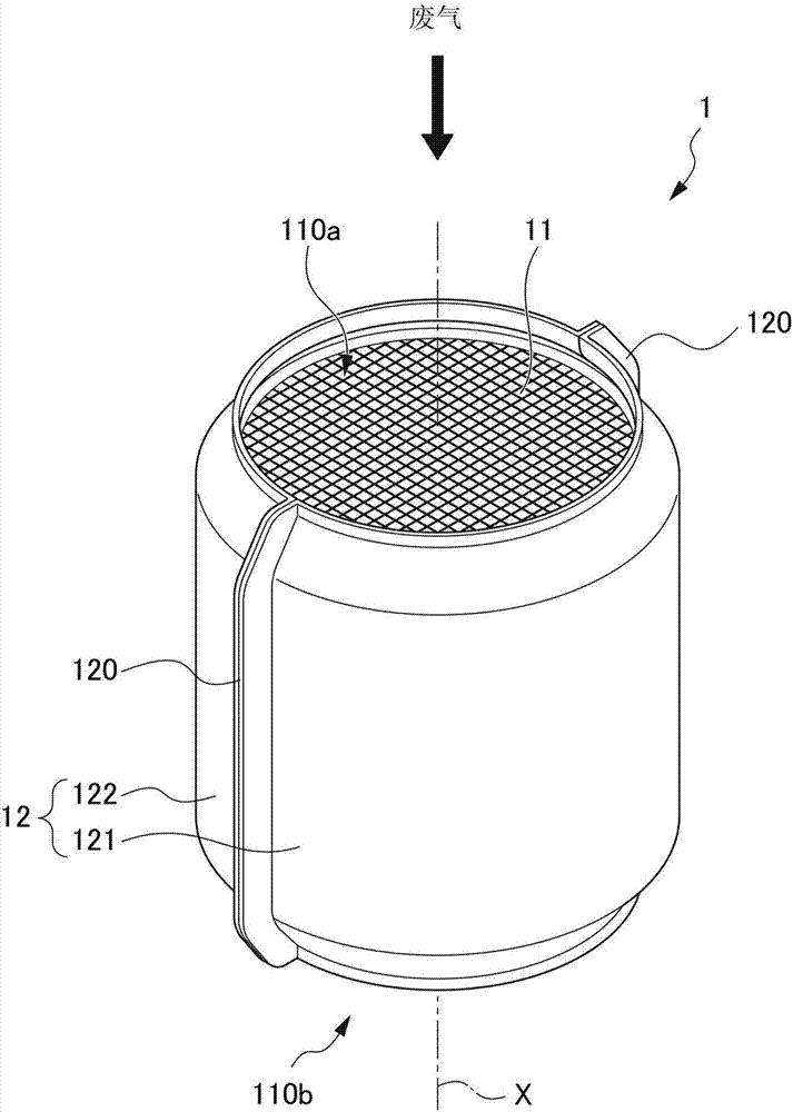
[0039] figure 1 It is a perspective view of an exhaust gas purification device for an internal combustion engine according to a first embodiment of the present invention. The exhaust gas purification device 1 for an internal combustion engine according to the present embodiment is installed in the exhaust pipe of a gasoline engine (hereinafter referred to as "engine") as an internal combustion engine (not shown in the figure) to control the exhaust gas flowing through the exhaust pipe. A gasoline particulate filter (hereinafter referred to as "GPF") that captures particulate matter (hereinafter referred to as "PM") or non-combustible dust (Ash).

[0040] The exhaust gas purifying device 1 is provided in an exhaust pipe extending downward along the side surface of the engine on the vehicle front side immediately below the engine (not shown). That is, the exhaust gas purification device 1 is installed in the exhaust pipe with the flow direction of the exhaust gas directed downw...

no. 2 Embodiment approach

[0082] Figure 4 It is an axial sectional view of the exhaust gas purification device 2 according to the second embodiment of the present invention. and, Figure 5 yes Figure 4 An enlarged view of the downstream peripheral portion in .

[0083] as it should Figure 4 and Figure 5 As shown, the exhaust gas purifying device 2 of the second embodiment has the same structure as the first embodiment except that the structure of the outer peripheral portion P is reversed on the upstream side and the downstream side compared with the first embodiment. That is, in the present embodiment, the holding member 23 is arranged so that the position of the downstream end 232 of the holding member 23 in the central axis X direction overlaps with the position of the sealing region SR in the downstream inclined portion 212b in the central axis X direction. .

[0084] The exhaust gas purification device 2 of this embodiment is manufactured by the same manufacturing method as the exhaust g...

no. 3 Embodiment approach

[0089] Figure 6 It is an enlarged view of the upstream side outer peripheral part in the axial cross-sectional view of the exhaust gas purification device 3 according to the third embodiment of the present invention. Figure 7 It is a figure which looked at the honeycomb carrier 31 of the exhaust gas purification apparatus 3 of 3rd Embodiment from the upstream side. Figure 8 It is a perspective view of the upstream side outer peripheral part in the honeycomb carrier 31 of the exhaust gas purification apparatus 3 of 3rd Embodiment.

[0090] The exhaust gas purifying device 3 of the third embodiment has the same structure as the first embodiment except that the structure on the upstream side of the outer peripheral portion P and the structure on the upstream side of the case member 32 are different from those in the first embodiment.

[0091] like Figure 6 to Figure 8 As shown, the honeycomb carrier 31 of the present embodiment has a linear portion 313 extending in the cent...


PUM


Abstract

The invention provides an exhaust gas purifying device for an internal combustion engine. The device is capable of ensuring sufficient filter effective capacity and exhaust gas purifying capability and reliably holds a honeycomb carrier in a casing member and is capable of reliably capturing a particulate matter or dust, and can keep the wind erosion of the part. The honeycomb carrier (11) includes an outer peripheral portion (P) having inclined portions (112a, 112b) formed on the outer peripheral side of both end faces of a central axis (X) direction, and the closer to the outer peripheral side of the honeycomb carrier, the larger the cross section vertical to the central axis is. An outer peripheral portion is held on the inner wall of a housing member (12) by means of a holding member (13), and the inclined portion has a sealing area (SR) and an open area (OR) which is configured on the periphery of the sealing area and is not sealed. The holding member (13) is configured that the position of at least one of the upstream end (131) and the downstream end (132) in the direction of the central axis and the position of the sealing area in the inclined portion on the central axis direction are overlapped.

Description

technical field [0001] The invention relates to an exhaust gas purification device of an internal combustion engine. Background technique [0002] Conventionally, there is known an exhaust gas purifying device for an internal combustion engine comprising a honeycomb carrier carrying an exhaust gas purification catalyst and having a filter function, and a cylindrical case member that accommodates the honeycomb by means of a holding member. carrier. As the honeycomb carrier, a so-called wall-flow type honeycomb carrier in which the inlet-side openings and the outlet-side openings of adjacent cell cells are alternately sealed is used. When housing the honeycomb carrier in the case member, it is important to securely hold the honeycomb carrier in the case member. [0003] As a technique for holding the honeycomb carrier in the housing member, generally, a mesh ring or the like is used. However, when a net ring or the like is used, the entire filter cannot be efficiently used,...

Claims


Application Information

Patent Timeline
Patent Type & Authority Applications(China)
IPC IPC(8): F01N3/022
CPCF01N3/0222F01N3/2825F01N3/2853F01N13/1888F01N2330/06F01N2330/32
Inventor 畠山由章
Owner HONDA MOTOR CO LTD
Why Eureka
Try Eureka