Check patentability & draft patents in minutes with Patsnap Eureka AI!

High resolution negative level detection circuit

A detection circuit, high-resolution technology, applied in the measurement of current/voltage, measurement device, measurement of electrical variables, etc., can solve problems such as difficult detection, achieve accurate detection, and meet application requirements.

Inactive Publication Date: 2017-08-22
UNIV OF ELECTRONICS SCI & TECH OF CHINA +1
View PDF16 Cites 9 Cited by
  • Summary
  • Abstract
  • Description
  • Claims
  • Application Information

AI Technical Summary

Problems solved by technology

Among them, the detection of the drain-source voltage of the step rectifier at the -5mV level is a major difficulty

Method used


Image

  • High resolution negative level detection circuit
  • High resolution negative level detection circuit
  • High resolution negative level detection circuit

Examples


Embodiment Construction

[0034] Below in conjunction with specific embodiment and accompanying drawing, describe technical solution of the present invention in detail:

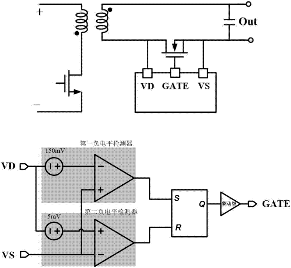
[0035] The present invention proposes a high-resolution negative level detection circuit, which can realize figure 1 The second negative level detector shown is for accurate detection of the drain-source voltage of the synchronous rectifier when it is greater than -5mV.

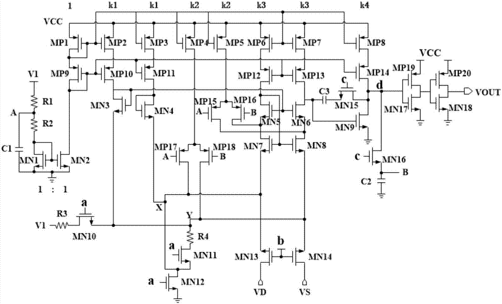
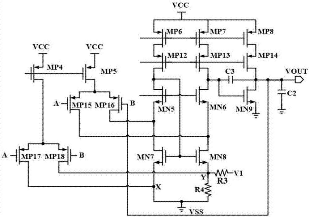
[0036] The circuit diagram of the negative level detection circuit proposed by the present invention is as follows figure 2 As shown, it includes a bias circuit, an operational amplifier containing an offset sampling unit, a switch control unit, a VDS sampling tube, an inverter circuit, an offset generating resistor R4, and a trimming resistor R3; wherein, the inverter circuit in this embodiment includes The seventeenth NMOS transistor MN17, the eighteenth NMOS transistor MN18, the nineteenth PMOS transistor MP19, and the twentieth PMOS transistor MP20, the gates o...


PUM


Abstract

The invention provides a high resolution negative level detection circuit, and belongs to the technical field of power supply management. The circuit works in a clamping operational amplification mode and a comparator mode in a period, and voltage drop deltaVR4 generated on a detuning generation resistor R4 is copied through a mode switching way so that negative level detection under the condition that the drain-source voltage of a synchronization adjustment pipe is -5mV can be realized; a differential pair formed by a seventeenth PMOS transistor MP17 and an eighteenth PMOS transistor MP18 is introduced so as to enable the voltage drop deltaVR4 on the detuning generation resistor R4 to be constant; besides, a trimming resistor R3 is introduced to trim the voltage drop deltaVR4 of the detuning generation resistor R4 so as to eliminate the influence caused by the process deviation. Accurate negative level detection can be realized and the resolution can be the millivolt level so that the application requirements for an adaptive synchronous rectification control circuit can be met.

Description

technical field [0001] The invention belongs to the technical field of power management, and in particular relates to a high-resolution negative level detection circuit. Background technique [0002] Synchronous rectification technology uses low on-resistance MOSFETs to replace conventional diodes or Schottky tubes, which can greatly reduce the power consumption of the rectification part, improve the performance of the converter, and achieve high efficiency of the power supply. A circuit topology using self-driven synchronous rectification technology such as figure 1 As shown, the chip samples the drain and source voltages of the synchronous rectifiers, and controls the gate of the synchronous rectifiers through internal logic to realize the opening and closing of the synchronous rectifiers. The specific internal logic is: when the first negative level detector detects the drain-source voltage V of the synchronous rectifier DS When <-150mV, the gate output GATE of the s...

Claims


Application Information

Patent Timeline
IPC IPC(8): G01R19/25
CPCG01R19/2503
Inventor 明鑫张文林鲁信秋张宣王卓张波
Owner UNIV OF ELECTRONICS SCI & TECH OF CHINA
Features
  • R&D
  • Intellectual Property
  • Life Sciences
  • Materials
  • Tech Scout
  • Unparalleled Data Quality
  • Higher Quality Content
  • 60% Fewer Hallucinations
Learn More