
Sensor used for magnetic conductivity measurement and measurement method thereof

A measurement method and sensor technology, applied in magnetic properties measurement, permeability measurement, etc., can solve the problems of large system error of self-inductance/mutual inductance, long processing and preparation cycle, and low accuracy of magnetic permeability measurement, so as to facilitate structural optimization , avoid the edge effect at both ends, and facilitate the effect of parameter correction

Inactive Publication Date: 2017-08-22
TIANJIN UNIV
View PDF8 Cites 9 Cited by
  • Summary
  • Abstract
  • Description
  • Claims
  • Application Information

AI Technical Summary

Problems solved by technology

[0003] The existing magnetic permeability measurement sensors and methods are affected by sample processing and sensor production, and the measurement accuracy of magnetic permeability is not high
First, the processing and preparation cycle of the sample is long, and the machining accuracy will be transmitted to the magnetic permeability measurement; second, the sensor mostly adopts the coil form of a long solenoid and a ring solenoid, and its self-inductance / mutual inductance calculation is too dependent on The self-inductance / mutual inductance calculation formulas of ideal coils, and these formulas are only applicable to coils that meet specific conditions, without considering the influence of the edge effect of the electromagnetic field at both ends of the finite-length coil, resulting in a large system error in the calculation of self-inductance / mutual inductance, error It can even reach more than 10%

Method used


Image

  • Sensor used for magnetic conductivity measurement and measurement method thereof
  • Sensor used for magnetic conductivity measurement and measurement method thereof
  • Sensor used for magnetic conductivity measurement and measurement method thereof

Examples


Embodiment Construction

[0013] The sensor and measurement method for magnetic permeability measurement of the present invention will be described with reference to the drawings and embodiments.

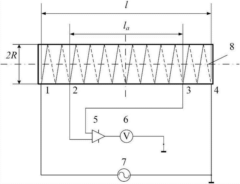
[0014] The structure of the sensor used for magnetic permeability measurement of the present invention is: the sensor includes a four-tap solenoid coil 8, and the solenoid coil 8 draws four taps sequentially from top to bottom, and the first tap in the four taps 1 is connected to the excitation current source 7, the fourth tap 4 is connected to the ground potential to form a current loop, the second tap 2 and the third tap 3 are connected to the input of the instrumentation amplifier 5 to obtain a differential voltage, and are connected to the voltage measurement module 6. The voltage measurement module 6 is one of an LCR meter, a digital multimeter or an instrument with an AC voltage measurement function.

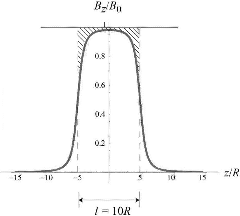
[0015] For the case where the solenoid coil 8 is infinitely long, its diameter is recorded as R, and ...


PUM


Abstract

The invention provides a sensor used for magnetic conductivity measurement. The sensor comprises a four-tap solenoid coil. Four taps are led out of the solenoid coil from the top to the bottom in turn. The first tap of the four taps is connected with an excitation current source which is connected with the ground. The fourth tap is connected with the ground potential of the excitation current source so as to form a current loop. The second tap and the third tap are connected with the input end of an instrument amplifier to acquire differential voltage and connected with a voltage measurement module. The invention also provides a measurement method using the sensor used for magnetic conductivity measurement. The effects of the sensor used for magnetic conductivity measurement are that the four-tap solenoid sensor is simple and feasible and can directly measure the magnetic conductivity of particle / powder material without preparing a magnetic core of the specific shape in advance; the physical model of the sensor is clear, and the relational expression between the induction value and the measured medium magnetic conductivity can be determined by the analytic formula so that structural optimization and parameter correction are facilitated; and the middle tap performs measurement so that the influence of the edge effect of the two ends of the solenoid can be avoided and the more accurate measurement result can be acquired.

Description

technical field [0001] The invention relates to a sensor and a measuring method for magnetic permeability measurement, especially for accurate measurement of magnetic permeability of particle / powder materials. Background technique [0002] The magnetic permeability parameter is a very important electromagnetic characteristic parameter, which is measured accurately and has great significance. Most of the existing magnetic permeability measurement methods are aimed at the measurement of coil core materials. The test samples are prefabricated into specific shapes, such as rods, rings, etc., which are used as the core of the coil to measure the self-inductance / mutual inductance; and then use The relationship of the coil inductance to the magnetic permeability of the core material determines the magnetic permeability of the material. Magnetic permeability measurement has applications in many fields, such as electromagnetic non-destructive testing of metal structural parts, proce...

Claims


Application Information

Patent Timeline
IPC IPC(8): G01R33/12
CPCG01R33/1223
Inventor 崔自强张威扬王化祥
Owner TIANJIN UNIV
Learn More