Method for controlling cutting force mutation in curve turning machining

A technology for controlling curves and cutting forces, applied in program control, computer control, general control systems, etc., can solve problems such as lack of applicability, high energy consumption, and affecting the processing quality of parts, and achieve the effect of efficiently completing curve turning processing

Active Publication Date: 2017-08-22
BEIJING RES INST OF PRECISE MECHATRONICS CONTROLS
View PDF6 Cites 3 Cited by
  • Summary
  • Abstract
  • Description
  • Claims
  • Application Information

AI Technical Summary

Problems solved by technology

Due to changes in the curvature of the workpiece contour curve, the cutting force is prone to large changes, which will cause cutting load impact on the tool and the workpiece, aggravate the wear and breakage of the blade, and even cause the tool to break, affecting the processing quality of the part and reducing production efficiency.
In the existing technology, when facing the outer circle turning and inner hole boring of the projectile, the cutting force will have a sudden change in the actual processing process. Usually, too small tool f

Method used


Image

  • Method for controlling cutting force mutation in curve turning machining
  • Method for controlling cutting force mutation in curve turning machining
  • Method for controlling cutting force mutation in curve turning machining

Examples


Embodiment

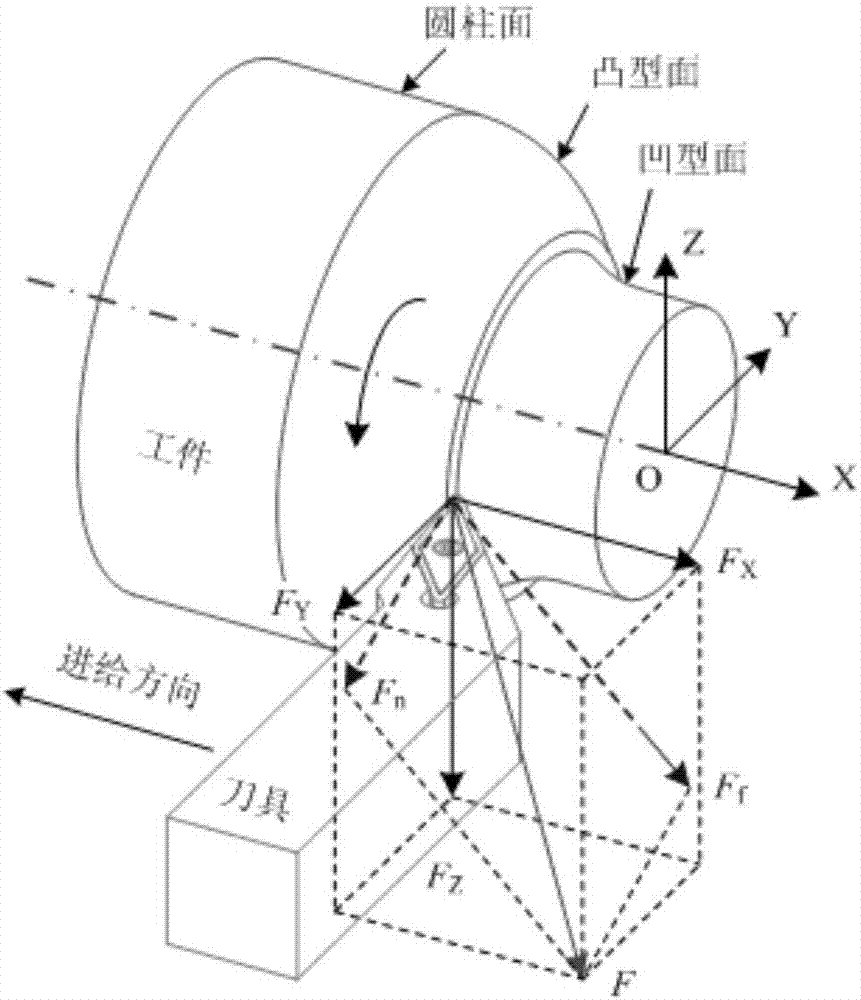
[0110] The test was carried out in the CNC precision turning center, and the cutting force F under the state of linear cutting was collected by the dynamometer on the world coordinate system OXYZ X1 , F Y1and F Z1 , the sampling frequency is 10KHz, the material of the test piece is 58SiMn high-strength steel, the rake angle of the tool is 0°, the rear angle is 5°, the main declination angle is 93°, the secondary declination angle is 52°, and the radius of the tool tip arc is 0.8mm.

[0111] 1. Conduct cutting force model coefficient calibration test

[0112] The factors and level design of the cutting force model coefficient calibration test are shown in Table 1, and the collected cutting force is expressed as a function of the cutting layer area, as shown in Figure 5 As shown, the cutting force model coefficients are calibrated according to the above calibration method, and the double exponential function

[0113]

[0114] Fit the coefficients of the cutting force mode...


PUM


Abstract

The invention discloses a method for controlling a cutting force mutation in curve turning machining. The method comprises the steps of adopting a B-spline curve method to perform parameterized processing on a cutting edge and a workpiece contour curve, establishing a unified computing model containing key geometric parameters, analyzing constrained relationships between coefficients of a cutting force model and a force vector, a speed vector and a chip flow vector, proposing a cutting force model coefficient calibration method, further determining cutting force model coefficients, judging a position where mutation of the cutting force occurs during the actual curve machining process by means of the established cutting force model, and further adjusting a feed amount of a cutter at the cutting force mutation position so that variation of the cutting force tends to be stable at the position. Compared with the application of a linear cutting modeling technology at present, the method provided by the invention can complete the curve turning machining efficiently.

Description

technical field [0001] The invention relates to a method for controlling sudden change of cutting force in curve turning, which belongs to the field of curve turning technology. Background technique [0002] Curve turning is a common processing technology in the industrial fields such as weapons and vehicles, such as turning the outer circle of the projectile, turning the convex and variable ellipse piston profile, etc. Due to changes in the curvature of the workpiece contour curve, the cutting force is prone to large changes, causing cutting load impacts on the tool and the workpiece, aggravating the wear and breakage of the blade, and even causing the tool to break, affecting the processing quality of the part and reducing production efficiency. In the existing technology, when facing the outer circle turning and inner hole boring of the projectile, the cutting force will have a sudden change in the actual processing process. Usually, too small tool feed rate is used to av...

Claims


Application Information

Patent Timeline
IPC IPC(8): G05B19/408
CPCG05B19/4086
Inventor 罗智文黄玉平徐强郑继贵侍威
Owner BEIJING RES INST OF PRECISE MECHATRONICS CONTROLS
Why Eureka
Try Eureka