Sleeve grinding fixture

A technology for grinding jigs and sleeves, which is applied in the field of tooling fixtures, can solve the problems of powder debris that cannot be cleaned in time, the diameter of the inner hole of the sleeve is limited, and the efficiency of clamping and dismounting is low, so as to improve the efficiency of clamping and dismounting and the scope of use. wide, improve the effect of grinding quality

Active Publication Date: 2017-08-25
张家港市宇安精密机械有限公司
View PDF13 Cites 5 Cited by
  • Summary
  • Abstract
  • Description
  • Claims
  • Application Information

AI Technical Summary

Problems solved by technology

[0005] However, there are still certain defects in the above scheme: 1. When clamping or dismounting the sleeve, it is necessary to disassemble the loading and unloading nut and the clamping cone from the mandrel before the sleeve can be clamped onto the mandrel Or disassembled from the mandrel, the operation is cumbersome, and the efficiency of clamping and disassembly is low; 2. The diameter of the inner hole of the applicable sleeve is limited, and the scope of use is small; 3. The powder debris generated during the grinding process cannot be cleaned in time. impact grinding

Method used


Image

  • Sleeve grinding fixture
  • Sleeve grinding fixture

Examples


Embodiment Construction

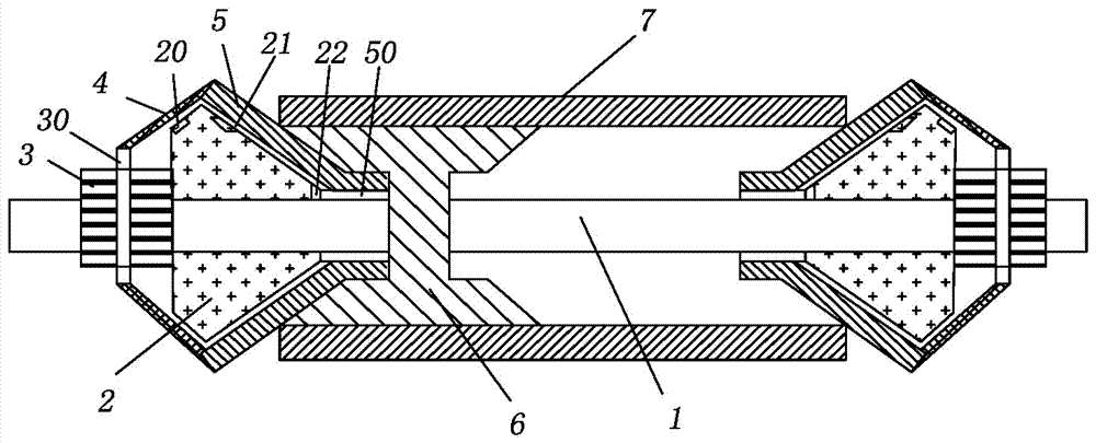
[0015] The reference signs in the drawings of the description include: mandrel 1, air bag 2, nut 3, support rod 4, fixed plate 5, air inlet 20, air outlet 21, air blowing hole 22, grinding head 6, grinding part 60, circle Ring 30, communication hole 50, sleeve 7.

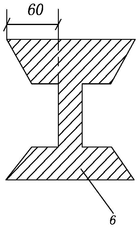
[0016] The sleeve grinding fixture provided by this embodiment, such as figure 1 As shown, it includes a cylindrical mandrel 1, the middle section of the mandrel 1 is a smooth surface, and is slidably connected with a grinding head 6, and its structure is as follows figure 2 As shown, the disc in the middle of the grinding head 6 is set to grind the inner hole of the sleeve 7 in the circumferential direction, and both sides of the middle of the grinding head 7 are provided with protruding grinding parts 60 (when the fixed plate 5 and the sleeve 7 are in contact with each other) At this time, a cavity will be formed, and the grinding part 60 can enter this cavity, thereby grinding the two ends of the inner hole of ...


PUM


Abstract

The invention relates to the technical field of work fixtures, and provides a sleeve grinding fixture. The sleeve grinding fixture comprises a cylindrical mandrel and two deformation mechanisms which are the same and are oppositely arranged on the mandrel. Each deformation mechanism comprises a gas bag, a nut, a plurality of supporting rods and a plurality of fixing plates. The nuts are connected with the mandrel in a threaded mode. The supporting rods are all hinged to the nuts and can rotate relative to the nuts. One ends of the fixing plates are hinged to the mandrel, and the other ends of the fixing plates are hinged to the supporting rods. The multiple fixing plates can form a cone around the mandrel and further be used for fixing a sleeve. The gas bags comprise gas inlets used for leading in gas and gas outlets used for blowing the gas to the outer circle of the sleeve, and the gas bags are arranged in the cone. According to the technical scheme, the sleeve grinding fixture provided by the invention is easy to operate, clamping and dismounting efficiency can be effectively improved, the range of application is wide, and grinding chips can further be cleared up in time.

Description

technical field [0001] The invention relates to the technical field of fixtures, in particular to a sleeve grinding fixture. Background technique [0002] The socket is a tool commonly used in automobile maintenance, and is often used to tighten or remove screws. Its structure usually includes an inner hole and an outer circle, the inner hole is mainly used for supporting and guiding, and the outer circle is generally used to contact other parts to play a supporting role. When processing the sleeve, it is usually necessary to clamp the sleeve to grind its outer circle and inner hole, and it is necessary to ensure the coaxiality of the outer circle and inner hole. However, due to the difficulty of clamping, it is often difficult to achieve shape and position tolerances (i.e. shape tolerance and position tolerance) requirements. [0003] The traditional method is to design the mandrel of the fixture into a cylindrical shape, but there must be a gap between the outer circle o...

Claims


Application Information

Patent Timeline
Patent Type & Authority Applications(China)
IPC IPC(8): B24B37/27
CPCB24B37/27Y02P70/10
Inventor 涂金华张成伟孙少辉王朝军
Owner 张家港市宇安精密机械有限公司
Why Eureka
Try Eureka