Elevator traction machine

A technology of elevator traction machine and casing, which is applied to elevators, elevators, transportation and packaging in buildings, etc. It can solve the problems of large impact force when stopping and stopping, coupling damage and impact, and reduction box impact, etc. problem, to achieve the effect of precise stop position, weakening impact and avoiding damage

Active Publication Date: 2017-08-25
HUBEI UNIV OF SCI & TECH
View PDF8 Cites 1 Cited by
  • Summary
  • Abstract
  • Description
  • Claims
  • Application Information

AI Technical Summary

Problems solved by technology

[0003] The existing elevator traction machine has the following problems: 1. The brake of the traditional elevator traction machine is electronically controlled, and the traction machine is located between the elevator car and the wall, and there is a lot of dust and debris, especially when it falls from the elevator door. 2. The brake of the traditional elevator traction machine has no passive safety device. When abnormal conditions such as power failure occur, the elevator car is in danger of falling; 3. The traditional elevator traction The brakes of the machine are used to brake the decelerated rotating shaft to achieve overall braking. The decelerated rotating shaft has a smaller speed and the braking effect is more obvious. However, when the decelerating end of the rotating shaft is braked, the impact on the reduction box is relatively large. , the damage and impact on the coupling is greater; 4. The coupling of the traditional elevator traction machine generally does not have a buffer function. Even if some couplings have a buffer function, the buffer cannot be buffered according to the actual situation of the elevator, that is, , when the elevator stops up and down, the impact force is different. The impact force of the down stop is relatively large, and it is not easy to avoid. The impact force of the down stop is small, but rebound is not allowed. If there is rebound, give Passengers have a stronger sense of weightlessness, which leads to discomfort when taking the elevator; 5. The structure of the reducer of the traditional elevator traction machine is complicated, and it is generally realized by bevel gears. The reduction ratio is obtained through multiple reductions, sacrificing part of the transmission stability

Method used


Image

  • Elevator traction machine
  • Elevator traction machine
  • Elevator traction machine

Examples


Embodiment Construction

[0037] The following are specific embodiments of the present invention and in conjunction with the accompanying drawings, the technical solutions of the present invention are further described, but the present invention is not limited to these embodiments.

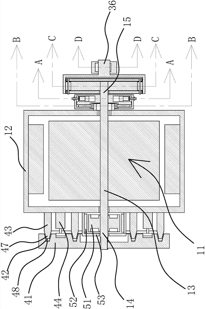
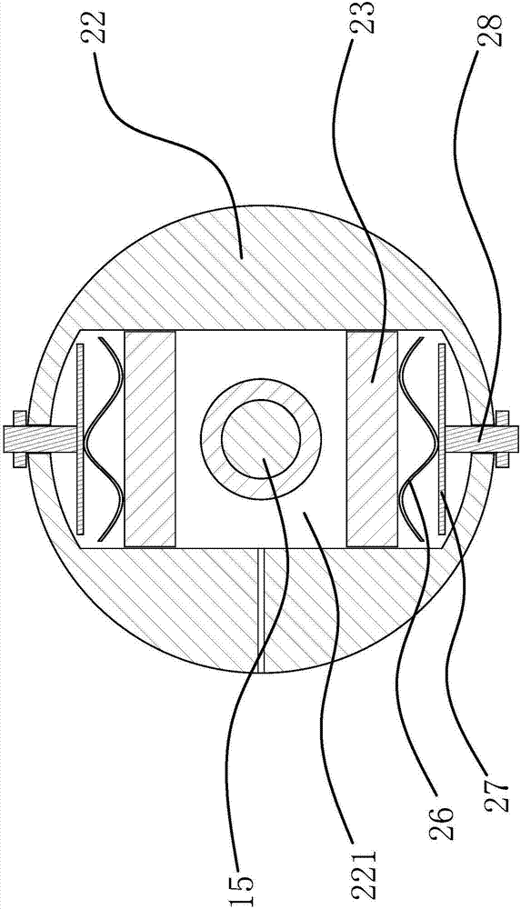
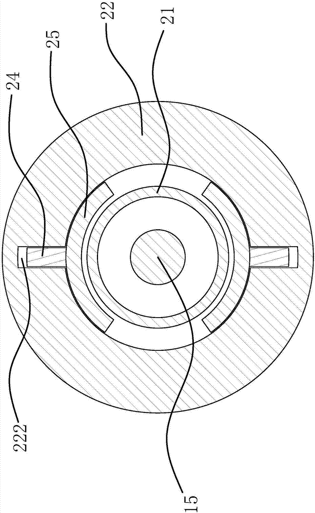
[0038] like figure 1 , figure 2 and image 3 As shown, the elevator traction machine includes a motor 11, a casing 12 and a rotating shaft 13 on the motor 11, a speed reducer and a brake are arranged between the casing 12 and the rotating shaft 13, and the rotating shaft 13 has a control end 14 protruding from the casing 12 and the output end 15, the output end 15 is provided with a passive safety device, the passive safety device includes a brake disc one 21 fixed on the casing 12 and a speed limiting box 22 fixed on the rotating shaft 13, and the speed limiting box 22 is evenly arranged There are several sliding chambers 221, each sliding chamber 221 is provided with a slidable counterweight valve core 23, and the hou...


PUM


Abstract

The invention provides an elevator traction machine and belongs to the technical field of motors. The technical problem that an existing elevator traction machine is poor in safety is solved. The elevator traction machine comprises a motor. The motor is provided with a machine shell and a rotating shaft. A speed reducer and a brake are arranged between the machine shell and the rotating shaft. The rotating shaft stretches out of the control end and the output end of the machine shell. The output end is provided with a passive safety device. The passive safety device comprises a first brake disc fixed to the machine shell and a speed limiting box fixed to the rotating shaft. A plurality of sliding cavities are evenly formed in the speed limiting box. Each sliding cavity is internally provided with a balance weight valve element capable of sliding. The machine shell is further provided with guide cavities in one-to-one correspondence with the sliding cavities. The sliding cavities communicate with the corresponding guide cavities. Valve posts are in sliding connection with the interiors of the guide cavities and connected with brake pads. The guide cavities and the sliding cavities are filled with hydraulic oil. The elevator traction machine has the advantage of being good in safety performance.

Description

technical field [0001] The invention belongs to the technical field of motors and relates to an elevator traction machine. Background technique [0002] The elevator traction machine is the power equipment of the elevator, also known as the elevator host. The function is to convey and transmit power to make the elevator run, control the elevator car to stop, etc. It is composed of motor, brake, coupling, reduction box, traction wheel, frame, guide wheel and auxiliary turning hand wheel. The guide wheels are generally installed on the frame or the load-bearing beam under the frame. Some of the turning hand wheels are fixed on the motor shaft, and some are usually hung on the nearby wall, and then set on the motor shaft when in use. [0003] The existing elevator traction machine has the following problems: 1. The brake of the traditional elevator traction machine is electronically controlled, and the traction machine is located between the elevator car and the wall, and th...

Claims


Application Information

Patent Timeline
Patent Type & Authority Applications(China)
IPC IPC(8): B66B11/04B66B5/18B66B5/04
CPCB66B5/044B66B5/18B66B11/0453
Inventor 孟鹏周国鹏
Owner HUBEI UNIV OF SCI & TECH
Why Eureka
Try Eureka