Water-cooled engine block

A water-cooled engine and cylinder block technology, applied in engine components, machines/engines, cylinders, etc., can solve the problems of limited contact area between cooling water and cylinder block, unsatisfactory heat dissipation effect, and large oil consumption, so as to enhance heat dissipation and cooling effect. , Improve heat dissipation effect and heat dissipation efficiency, reduce the effect of burning oil

Active Publication Date: 2020-05-19
GUANGAN YAOYE MACHINERY MFG CO LTD
View PDF7 Cites 0 Cited by
  • Summary
  • Abstract
  • Description
  • Claims
  • Application Information

AI Technical Summary

Problems solved by technology

[0007] However, the contact area between the cooling water and the cylinder block is limited, resulting in unsatisfactory heat dissipation; and due to the limitation of the manufacturing process, the cooling water channel part of the cylinder block is set in the air, which makes it very easy for the engine to make the cylinder block during operation. The hole is deformed, resulting in high oil consumption, engine scuffing and other failures
In particular, when the motorcycle water-cooled engine cylinder is in use, oil burning and cylinder scuffing often occur. After inspection by professional technicians, it is largely caused by the deformation of the cylinder bore of the motorcycle cylinder, because the cooling channel part of the water-cooled cylinder 2 The working part of / 3 is suspended, and it is easy to deform under the action of force, which causes the above phenomenon when the motorcycle is running

Method used


Image

  • Water-cooled engine block
  • Water-cooled engine block
  • Water-cooled engine block

Examples


Embodiment

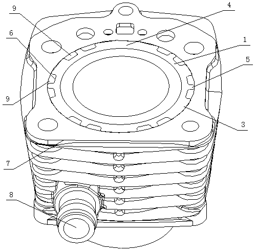
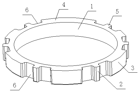
[0039] Such as figure 1 , figure 2 Shown, a kind of water-cooled engine cylinder block, it comprises the cylinder body 7 that is provided with cylinder hole and the support ring body 1 that is annular cylindrical shape, and described cylinder body 7 is provided with inwardly on one end surface near the cylinder head body. The cylinder body waterway 9 is recessed in the shape of an annular cavity, and the cylinder body waterway 9 surrounds the outside of the cylinder hole, and the other end of the cylinder body 7 is provided with a water inlet communicating with the cylinder body waterway 9 8. The support ring body 1 is located at the opening of the cylinder water channel 9, and its end face away from the cylinder water channel 9 is flush with the opening surface of the cylinder water channel 9, and the inner side of the ring is in line with the cylinder water channel 9. The inner side of the ring of the cylinder water channel 9 is closely fitted.

[0040] The outer ring of ...


PUM


Abstract

The invention relates to a water cooling engine cylinder. The water cooling engine cylinder comprises a cylinder body with a cylinder hole and an annular cylinder-shaped supporting ring body. A cylinder water way which is concaved inwards, is in the shape of an annular cavity and surrounds the cylinder hole is arranged on the end face of one end of the cylinder body, and a water inlet communicating with the cylinder water way is formed in the other end of the cylinder body. The supporting ring body is located at the opening position of the cylinder water way, and the ring inner side of the supporting ring body is closely attached to the ring inner side of the cylinder water way. A plurality of racks which protrude outwards and are closely attached to the ring outer side of the cylinder water way are arranged on the ring outer side of the supporting ring body. The multiple racks are distributed in the circumferential direction of the supporting ring body, and the supporting ring body and the racks are made of hard heat conduction materials. According to the product, the cylinder stress balance can be effectively guaranteed, the cylinder is firmer and more resistant to pressure, cylinder deformation due to the action of external force is avoided, and the phenomena of engine oil burning, scuffing and the like of an engine are reduced; the heat dissipation effect is better, the stability of the engine can be effectively improved, the supporting ring body and the cylinder water way are detachably connected, and maintaining and replacing are more convenient and rapid.

Description

technical field [0001] The invention relates to the field of engine cylinders, in particular to a water-cooled engine cylinder. Background technique [0002] At present, in the engine field, the cylinder block is the main part of the engine, which integrates the cylinder and the crankcase, and is the supporting framework for installing the piston, crankshaft and other parts and accessories. Among them, the working conditions of the cylinder block are very harsh, and it has to bear the sharp changes of pressure and temperature during the combustion process and the strong friction of the piston movement. Therefore, it should have the following properties: [0003] ①It has sufficient strength and rigidity, small deformation, and ensures the correct position of each moving part, normal operation, and low vibration and noise. [0004] ②Good cooling performance. [0005] ③ wear-resistant to ensure that the cylinder has a sufficient service life. [0006] In order to make the i...

Claims


Application Information

Patent Timeline
Patent Type & Authority Patents(China)
IPC IPC(8): F02F1/10
CPCF02F1/10
Inventor 李国贵李义赵世平向文强
Owner GUANGAN YAOYE MACHINERY MFG CO LTD
Why Eureka
Try Eureka