
Wind tunnel flow field observation system

An observation system and wind tunnel technology, applied in the field of fluid dynamics, can solve the problems that the three-dimensional flow field structure cannot be obtained from the image, the three-dimensional structure of the flow field cannot be obtained, and the structure of the gas flow field is affected.

Inactive Publication Date: 2017-08-25
NAT UNIV OF DEFENSE TECH
View PDF6 Cites 19 Cited by
  • Summary
  • Abstract
  • Description
  • Claims
  • Application Information

AI Technical Summary

Problems solved by technology

For the traditional observation method of adding liquid, the structure of the gas flow field may be affected, and the three-dimensional flow field structure cannot be obtained from the image; for the flow field observation method of adding particles, such as planar nanoparticle tracking Rayleigh scattering technology, particle velocity measurement Technology, etc., can only obtain the flow field structure of a certain plane of the flow field, and cannot obtain the three-dimensional structure of the flow field in one test

Method used


Image

  • Wind tunnel flow field observation system

Examples


Embodiment Construction

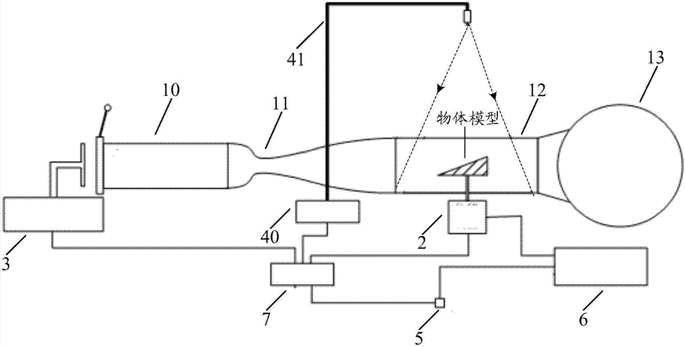
[0030] In order to enable those skilled in the art to better understand the technical solutions in the present invention, the technical solutions in the embodiments of the present invention will be clearly and completely described below in conjunction with the drawings in the embodiments of the present invention. Obviously, the described The embodiments are only some of the embodiments of the present invention, not all of them. Based on the embodiments of the present invention, all other embodiments obtained by persons of ordinary skill in the art without creative efforts shall fall within the protection scope of the present invention.

[0031] A wind tunnel flow field observation system provided by an embodiment of the present invention includes:

[0032] wind tunnel installation;

[0033] a displacement control device for controlling the positional movement of the object model in the wind tunnel device;

[0034] A tracer particle generating device for adding tracer particl...


PUM


Abstract

The invention discloses a wind tunnel flow field observation system which comprises a wind tunnel device, a displacement control device used for controlling the position movement of an object model in the wind tunnel device, a tracer particle generation device used for adding tracer particles to the wind tunnel device, a light source device used for shining light to the wind tunnel device, a shooting device used for shooting images of the flow field in the wind tunnel device, and an image processing device used for constructing a three-dimensional flow field structure image according to a sequence of flow field images shot by the shooting device and the position information of the object model recorded by the displacement control device. According to the wind tunnel flow field observation system of the invention, the position movement of the object model in the wind tunnel device is controlled by the displacement control device, a sequence of flow field images of the wind tunnel device are shot, a three-dimensional flow field structure image is constructed according to a sequence of flow field images shot and the position information of the object model recorded by the displacement control device, and therefore, the three-dimensional flow field structure of the flow field in the wind tunnel is obtained.

Description

technical field [0001] The invention relates to the technical field of fluid power, in particular to a wind tunnel flow field observation system. Background technique [0002] Wind tunnel test refers to an aerodynamic experiment method in which an object model, such as an aircraft, is set up in a wind tunnel to study gas flow and its interaction with the model to understand the aerodynamic characteristics of the actual object. Wind tunnel tests not only play an important role in the research and development of aerospace engineering, but also are widely used in transportation, wind energy utilization, etc. [0003] Flow field observation refers to the use of physical or chemical flow field display means to make the colorless and transparent airflow in a hypersonic / supersonic wind tunnel into a visible airflow for observation, recording and analysis. Using the flow field observation method, the physical image of the gas flow can be directly observed, thereby deepening the und...

Claims


Application Information

Patent Timeline
IPC IPC(8): G01M9/02G01M9/04
CPCG01M9/067
Inventor 陶渊范晓樯刘卫东熊冰周鑫蒙泽威李腾骥赵健
Owner NAT UNIV OF DEFENSE TECH
Learn More