
Glass smashing machine used for building industry

A pulverizer and pulverizer motor technology, applied in dryers, non-progressive dryers, drying solid materials, etc., can solve problems such as incomplete pulverization, low pulverization efficiency of glass pulverizers, and difficult disposal of glass waste, etc., and achieve an improvement Crushing effect, easy crushing, effect of increasing residence time

Inactive Publication Date: 2017-08-29
ANHUI YIQI SOFTWARE TECH
View PDF0 Cites 33 Cited by
  • Summary
  • Abstract
  • Description
  • Claims
  • Application Information

AI Technical Summary

Problems solved by technology

[0002] Human beings have learned to make and use glass for thousands of years. With the development of modern science and technology and glass technology and the improvement of people's living standards, the function of architectural glass is no longer just to meet the lighting requirements, but to have the ability to adjust light, heat preservation Heat insulation, safety, art decoration and other characteristics, with the continuous development of demand, glass molding and processing methods have also undergone new developments, so that the amount of glass used in buildings has increased rapidly, becoming the third largest after cement and steel. Building materials, however, the construction industry often produces a lot of glass waste. With the improvement of people's glass manufacturing technology, the quality of glass is getting better and better, and glass waste is becoming more and more difficult to deal with. The existing glass crushers often have low crushing efficiency. , the crushing is not thorough enough to meet people's needs

Method used


Image

  • Glass smashing machine used for building industry
  • Glass smashing machine used for building industry
  • Glass smashing machine used for building industry

Examples


Embodiment Construction

[0017] The following will clearly and completely describe the technical solutions in the embodiments of the present invention with reference to the accompanying drawings in the embodiments of the present invention. Obviously, the described embodiments are only some, not all, embodiments of the present invention. Based on the embodiments of the present invention, all other embodiments obtained by persons of ordinary skill in the art without making creative efforts belong to the protection scope of the present invention.

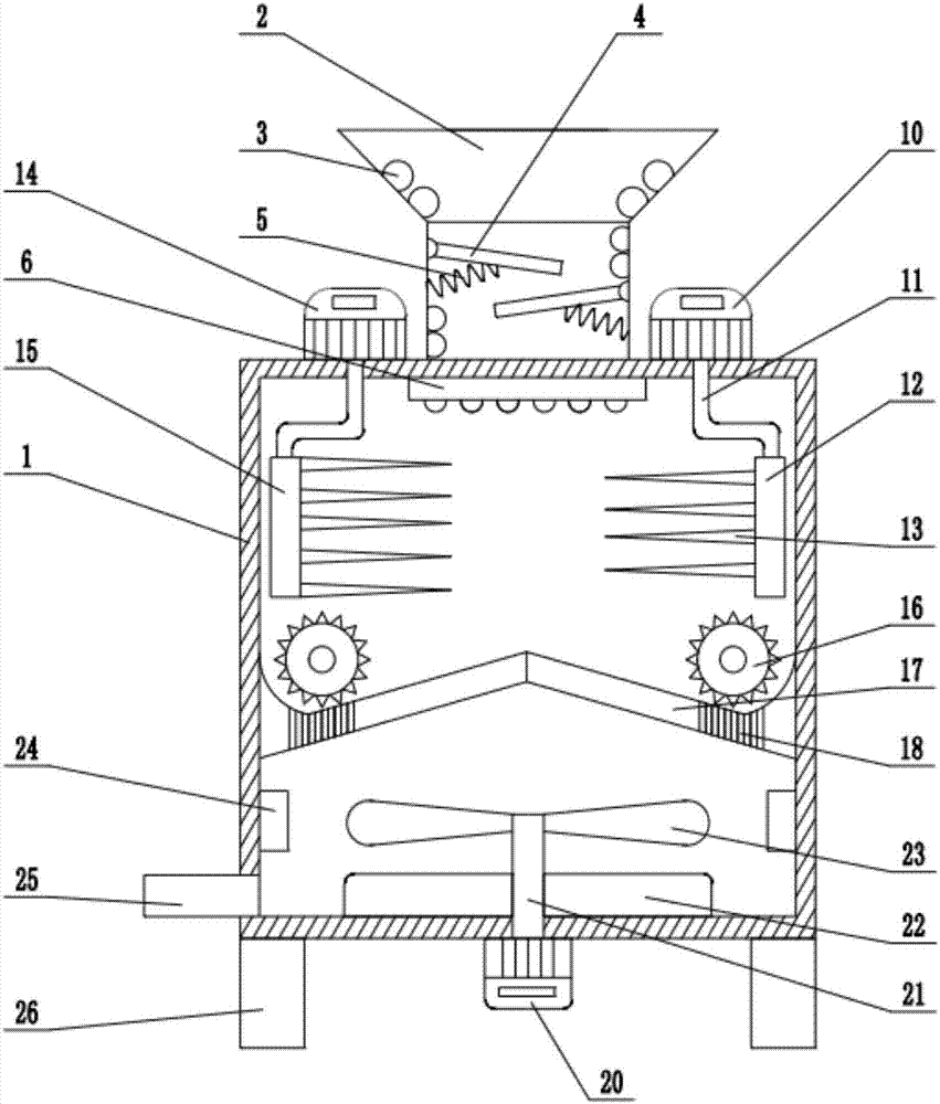
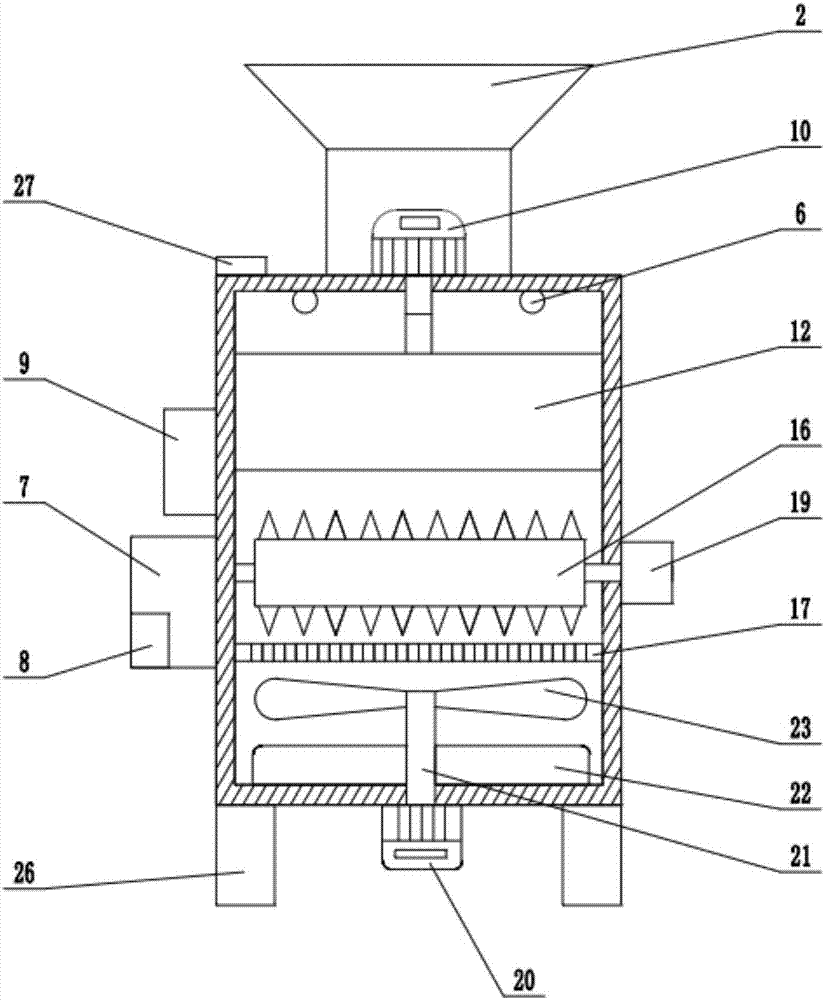
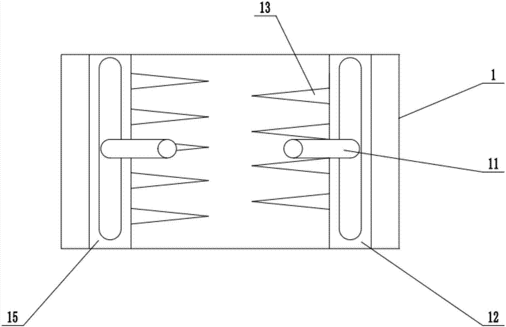
[0018] see Figure 1~3 , in an embodiment of the present invention, a glass pulverizer for the construction industry includes a housing 1, a feed port 2, a pulverizing drum 16, a guide plate 18, a pulverizing motor 19, a discharge port 25 and a leg 26; The top is fixedly connected with a feed port 2, and the inner wall of the feed port 2 is fixedly connected with an electric heating tube 3, which can heat the glass waste thrown in. The inner wall of the feed p...


PUM


Abstract

The invention discloses a glass smashing machine used for the building industry. The glass smashing machine comprises an outer shell, a feed inlet, a smashing roller, a guide plate, a smashing motor, a discharge outlet and supporting legs. The inner wall of the feed inlet is fixedly connected with an electric heating pipe. The top of the outer shell is fixedly connected with a water spray pipe. The upper surface of the outer shell is fixedly connected with a first crushing motor and a second crushing motor. The shaft extension ends of the first crushing motor and the second crushing motor are fixedly connected with crankshafts correspondingly. The outer shell is internally provided with a first crushing plate and a second crushing plate. Glass garbage is heated through the electric heating pipe, meanwhile, buffering plates and springs are matched, the retention time of the glass garbage in the feed inlet is prolonged, and the heating effect is improved; high-temperature glass is rapidly cooled through cold water, so that the glass becomes fragile and can be easily crushed, and the smashing effect is improved; the glass garbage between the first crushing plate and the second crushing plate can be crushed through crushing blades; and the glass garbage is further smashed through the smashing roller, so that the glass garbage is more thoroughly smashed.

Description

technical field [0001] The invention relates to construction waste processing equipment, in particular to a glass pulverizer for construction industry. Background technique [0002] Human beings have learned to make and use glass for thousands of years. With the development of modern science and technology and glass technology and the improvement of people's living standards, the function of architectural glass is no longer just to meet the lighting requirements, but to have the ability to adjust light, heat preservation Heat insulation, safety, art decoration and other characteristics, with the continuous development of demand, glass molding and processing methods have also undergone new developments, so that the amount of glass used in buildings has increased rapidly, becoming the third largest after cement and steel. Building materials, however, the construction industry often produces a lot of glass waste. With the improvement of people's glass manufacturing technology, ...

Claims


Application Information

Patent Timeline
IPC IPC(8): B02C18/02B02C4/02B02C19/18B02C23/02F26B11/16F26B25/04
CPCB02C18/02B02C4/02B02C19/186B02C23/02F26B11/16F26B25/04
Inventor 姚和中
Owner ANHUI YIQI SOFTWARE TECH
Learn More