Automatic combined wire welding equipment and welding method thereof

An automatic welding and combination wire technology, applied in welding equipment, metal processing equipment, conductors, etc., can solve the problems of unfixed wire spacing, difficult to straighten out, affecting high-frequency characteristics, etc., to achieve stable and good high-frequency characteristics and excellent products. The effect of high rate and high cost advantage

Pending Publication Date: 2017-08-29
惠州市升华科技有限公司
View PDF9 Cites 6 Cited by
  • Summary
  • Abstract
  • Description
  • Claims
  • Application Information

AI Technical Summary

Problems solved by technology

The welding between the main wire and the wiring is a relatively tedious and difficult work. Due to the short size of the welding wire and many solder joints, heat-shrinkable sleeves must be put on for direct butt welding. The welding efficiency is low, and it is easy to cause short circuits and joints. High-frequency impedance mutation and other electrical defects, low yield rate
[0003] The traditional welding method has several disadvantages: 1. Each wire needs to be put on a sleeve in advance, which is very time-consuming; 2. The butt welding of the wire requires skilled welding personnel to operate, and the labor cost is high; 3. After welding, it must be heated Shrink sleeve; 4. The wire sequence is chaotic, interacting with each other, and it is not easy to straighten out; 5. The entire interface length needs to be longer, and the appearance size and SR fix the wire end strength; 6. The wire spacing is not fixed, and the high-frequency impedance of the connecting part changes abruptly , affecting high-frequency characteristics, so most of the products cannot pass the eye diagram test

Method used


Image

  • Automatic combined wire welding equipment and welding method thereof
  • Automatic combined wire welding equipment and welding method thereof
  • Automatic combined wire welding equipment and welding method thereof

Examples


Embodiment Construction

[0018] In order to make the technical means, creative features, goals and effects achieved by the present invention easy to understand, the present invention will be further described below in conjunction with specific embodiments.

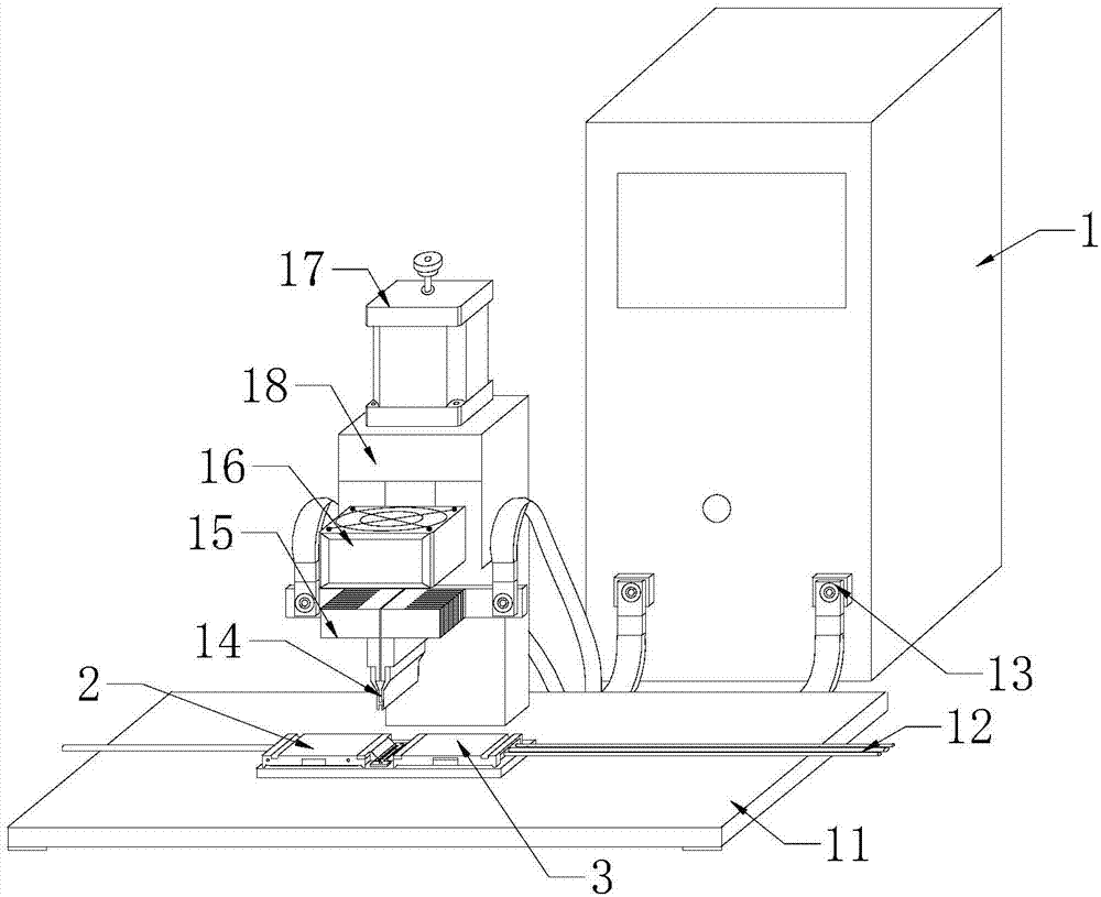
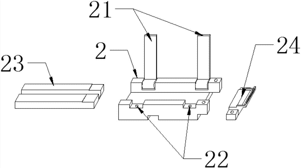
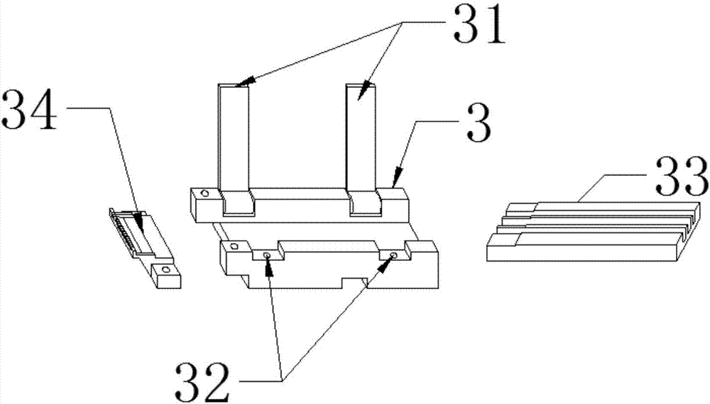
[0019] see Figure 1 to Figure 3 , the present invention provides a technical solution: a combined line automatic welding equipment, including a main box 1, a left wiring fixture 2 and a right wiring fixture 3, the front end of the main box 1 is provided with a welding machine base 11, the welding machine The base 11 is placed with a left wiring fixture 2 and a right wiring fixture 3, the front surface of the main chassis 1 is provided with a welding machine power electrode 13, the main chassis 1 is connected to the welding structure through the welding power supply electrode 13, and the welding structure is composed of two Knife row welding head 14, electrode radiator 15, cooling fan 16, stepping motor 18 and welding machine rail mechanism 18, st...


PUM


Abstract

The invention provides automatic combined wire welding equipment. The equipment comprises a main case, a left wire arranging jig and a right wire arranging jig, wherein a welding machine base is arranged at the front end of the main case; welding machine power supply electrodes are arranged on the front surface of the main case; the main case is connected with a welding structure through the welding machine power supply electrodes; the welding structure comprises a welding head with double rows of knives, an electrode radiator, a cooling fan, a stepping moving motor and a welding machine rail running mechanism; the stepping moving motor is arranged above the welding machine rail running mechanism; the welding head with double rows of knives is arranged at the front side of the welding machine rail running mechanism; the electrode radiator is arranged on the top of the welding head with double rows of knives; and the cooling fan is arranged on the top of the electrode radiator. The equipment provided by the invention has the following beneficial effects that joint size is short, so that the requirements for SR appearance and wire end fixing are met; the space between the wires is fixed and the wires are uncrossed, so that the high-frequency characteristic is stable and good; and the wire welding operation is standard and easy to learn.

Description

technical field [0001] The invention is an automatic welding device for a combined line, which belongs to the field of mechanical equipment. Background technique [0002] In addition to the main wire, the combined data line usually has various functional wiring and line-end connectors, and the lines are connected to each other to complete the transmission of digital and analog signals. The welding between the main wire and the wiring is a relatively tedious and difficult work. Due to the short size of the welding wire and many solder joints, heat-shrinkable sleeves must be put on for direct butt welding. The welding efficiency is low, and it is easy to cause short circuits and joints. High-frequency impedance mutation and other electrical defects, the yield rate is low. [0003] The traditional welding method has several disadvantages: 1. Each wire needs to be put on a sleeve in advance, which is very time-consuming; 2. The butt welding of the wire requires skilled welding ...

Claims


Application Information

Patent Timeline
Patent Type & Authority Applications(China)
IPC IPC(8): B23K3/00B23K3/08B23K3/02B23K101/38
CPCB23K3/00B23K3/02B23K3/08B23K3/087B23K2101/38
Inventor 翁科义
Owner 惠州市升华科技有限公司
Why Eureka
Try Eureka