Splash-proof dust-removing device for molten iron ditch slot

A technology of dust removal device and iron gutter, applied in the direction of dust collector, discharge device, etc., can solve the problems of poor working environment, unfavorable health of workers, and large environmental impact, so as to prevent strong light pollution, facilitate docking, and solve heat radiation. Effect

Active Publication Date: 2017-08-29
CHONGQING UNIVERSITY OF SCIENCE AND TECHNOLOGY
View PDF29 Cites 1 Cited by
  • Summary
  • Abstract
  • Description
  • Claims
  • Application Information

AI Technical Summary

Problems solved by technology

[0002]The metal smelting industry involves the transfer of the extracted molten metal. The diversion groove is used for drainage, and the molten iron flows in the groove to generate smoke and strong heat radiation. At the same time, strong light radiation and splashes are generated, which has a great impact on the environment and is not good for the health of the workers. The working environment of the workers is relatively harsh. technical solution

Method used


Image

  • Splash-proof dust-removing device for molten iron ditch slot
  • Splash-proof dust-removing device for molten iron ditch slot

Examples


Embodiment Construction

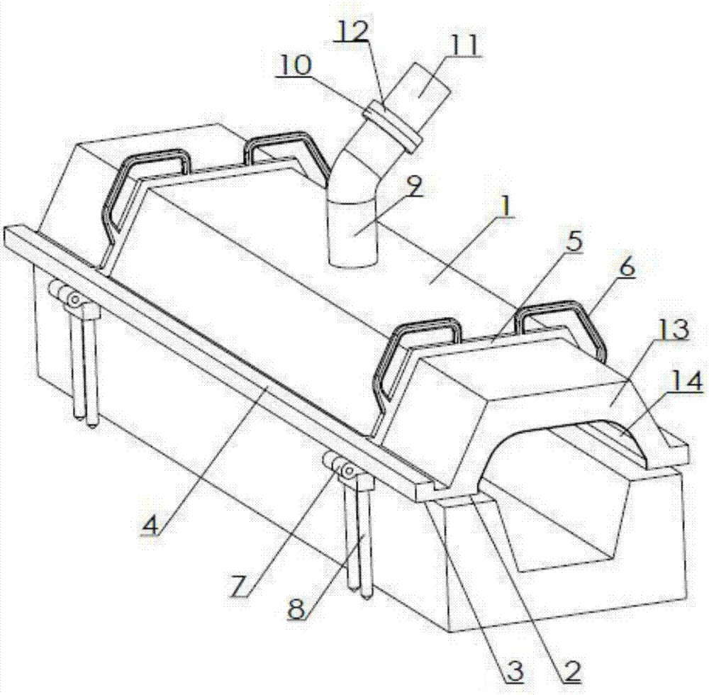
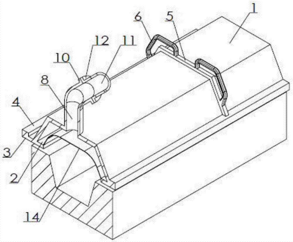
[0011] Examples of the present invention figure 1 , 2 As shown, the splash-proof and dust-removing device for the molten iron groove is provided with the molten iron groove and at least one section of the splash-proof cover, which can be arranged on the upper part of the molten iron groove in multiple sections to keep gaps, even for curved grooves, and the splash-proof cover is provided with The section extending along the iron launder is an inverted U-shaped outer cover 1 as a whole. The lower edges on both sides of the outer cover are respectively connected with inner edges 2 and outer edges 3, and the two outer edges are respectively connected with longitudinal side beams 4. At least two longitudinal side beams pass between the two longitudinal side beams. A roughly inverted U-shaped crossbeam 5 connected to the outer side of the outer cover is connected, and a wrench 6 is connected on the scale to form a structurally stable support. Stretch upwards and then to the exhaust...


PUM


Abstract

The invention discloses a splash-proof dust-removing device for a molten iron ditch slot. The splash-proof dust-removing device for the molten iron ditch slot is characterized in that the device comprises a molten iron slot and at least one section of splash-proof cover. Each splash-proof cover is provided with an outer cover stretching along the molten iron slot, wherein a whole cross section of the outer cover is of a reversed-U-shape. The lower edges of two sides of each outer cover are connected with an inner edge and an outer edge correspondingly. Two outer edges of the lower edges of two sides of each outer cover are connected with longitudinal edge beams correspondingly. Two longitudinal edge beams are connected therebetween through at least two transverse beams which are of reverse-U-shape roughly and are connected at the outer side of the outer cover. Spanners are connected on the transverse beams. The transverse beam at one side is connected with a pile drill inserted into ground through a hinge. Two ends of the outer cover are connected with end plates which are reverse-U-shaped on the whole correspondingly. Edges and inner edges are arranged in the outer cover, and the edges and the inner edges and the end plates are connected with an inner side metal net. Inward elastic steel wires are connected on the metal net. An air exhaust duct is arranged on the outer cover, wherein the air exhaust duct stretches upward and then stretches toward the inclined upward side away from one side of the hinge. The air exhaust duct is connected with a movably butt joint loop. The movably butt joint loop is connected with a fixed butt joint loop connected with an air intake duct in a butt joint mode. According to the splash-proof dust-removing device for the molten iron ditch slot, a better working environment can be created.

Description

technical field [0001] The invention relates to a tool for feeding molten iron into a hopper for metal smelting, in particular to a splash-proof and dust-removing device for molten iron grooves. Background technique [0002] The metal smelting industry involves the transfer of the refined molten metal. For example, the molten iron should be transferred away during iron smelting. During the transfer process, it must be drained through the diversion groove, and the molten iron flows in the groove. Smoke dust and strong heat radiation, together with strong light radiation and splash, have a great impact on the environment and are unfavorable to the health of workers. The working environment of workers is relatively harsh, and technical solutions are still needed. Contents of the invention [0003] In order to solve the above problems, the present invention provides a splash-proof and dust-removing device for molten iron grooves. [0004] The technical solution adopted in the...

Claims


Application Information

Patent Timeline
IPC IPC(8): C21B7/22C21B7/14
CPCC21B7/14C21B7/22
Inventor 柳浩秦跃林江青芳麦吉昌罗清明
Owner CHONGQING UNIVERSITY OF SCIENCE AND TECHNOLOGY
Why Eureka
Try Eureka