Knob electronic shift control device and shift signal encoder thereof

A gear position signal and encoder technology, which is applied in the direction of conversion sensor output, instruments, measuring devices, etc., can solve the difficulty of lightweight design and cost control of the knob electronic shifter, which is unfavorable for the generalization and modularization of the knob electronic shifter Design, reduction of utilization rate of electrical components and other issues, to achieve the effect of saving layout space, reducing related circuit electrical components, and reducing production costs

Active Publication Date: 2017-08-29
BEIJING CHANGAN AUTOMOBILE ENG TECH RES
View PDF8 Cites 7 Cited by
  • Summary
  • Abstract
  • Description
  • Claims
  • Application Information

AI Technical Summary

Problems solved by technology

[0011] It can be seen that this kind of knob electronic shifter requires a set of dedicated groove-type photoelectric switch circuits for each gear position, which not only consumes a large number of electrical components, but also takes up a lot of space on the PCB board. The lightweight design and cost control of the knob electronic shifter bring certain difficulties, and it is also not conducive to the expansion of other electrical functions. At the same time, more electrical components are arranged in the PCB board with limited space. The optimization of EMC performance also brings unfavorable factors; when the knob electronic shifter is rotated to a certain gear position, only the relevant lines of the gear position work, and the lines of other gear positions are idle, resulting in a decrease in the utilization rate of electrical components; when the number of gear positions When changing, the structure of BIM also needs to be changed accordingly, which is not conducive to the realization of the universal and modular design of the knob electronic shifter

Method used


Image

  • Knob electronic shift control device and shift signal encoder thereof
  • Knob electronic shift control device and shift signal encoder thereof
  • Knob electronic shift control device and shift signal encoder thereof

Examples


specific Embodiment 1

[0079] See Picture 9 , 10 , The total shift stroke of the track body 8 is β, and the stroke between adjacent gears is α. The gear signal encoder is equipped with three diffuse reflection type photoelectric switches 13, and the three diffuse reflection type photoelectric switches 13 are specifically The radial distance from the center axis of the track body may be different.

[0080] In the working area of ​​the code wheel 14, with the projection of the central axis of the track body on the plane of the code wheel 14 as the center of the circle, a gear interval can be set at a certain angle around the circumference, and each gear interval is fan-shaped. For example, set the gear interval I15, gear interval II16, gear interval III17, gear interval IV18, and gear interval in a clockwise direction at the interval angle α (the stroke between adjacent gear positions of the electronic knob shifter is also α). Gear interval V19, gear interval VI20, gear interval VII21, and gear interval...

specific Embodiment 2

[0094] See Picture 11 In this embodiment, the structure of the code wheel 14 can be regarded as the structure of the code wheel 14 in the specific embodiment 1 as the basis for adjusting the track angle, that is, the track II25 of the code wheel 14 in the specific embodiment 1 rotates clockwise θ angle, correspondingly, switch II13-2 also rotates clockwise by θ angle. Since the overlap of the edge of the track II25 with the edges of the track I24 and the track III26 increases, it is beneficial to the overall strength of the code wheel 14. At the same time, the connection strength between the outer ring 23 and the inner ring 27 can be improved, which can effectively reduce the code wheel. 14 Difficulty in manufacturing the mold, and the manufacturing process of the code plate 14 is improved. In this embodiment, the corresponding relationship between the gear position signal and the gear position is the same as in the first embodiment.

[0095] Among them, when a gear interval is...

specific Embodiment 3

[0108] See Picture 12 In this embodiment, the structure of the code wheel 14 can be regarded as obtained by adjusting the gear signal sequence based on the structure of the code wheel 14 in the first embodiment, so as to reduce the manufacturing cost, improve the manufacturing process, and strengthen the structural strength. The adjusted gear interval in the clockwise direction is: gear interval IV18, gear interval II16, gear interval VI20, gear interval V19, gear interval VIII22, gear interval III17, gear interval I15, gear Interval VII21.

[0109] In practical application, with its 5-gear knob electronic shifter, gear interval IV18, gear interval II16, gear interval VI20, gear interval V19, and gear interval VIII22 are effective working intervals, and gear intervals III17. Gear interval I15 and Gear interval VII21 are reserved intervals for extended gears. The application results are as follows:

[0110] When the knob body 6 is rotated to the P position: the gear interval IV18 ...


PUM


Abstract

The present invention discloses a shift signal encoder including a code disc and diffuse reflective photoelectric switches fixed to a PCB. The code disc is fixed at the bottom end of a track body and extends radially outwardly out of the outer periphery of the track body. The code disc is divided into a plurality of shift intervals in the circumferential direction, each shift is respectively provided with a shift interval, each shift interval corresponds to a shift signal, and the shift interval is provided with a hollow part and a coverage part according to the corresponding shift signal. When the shift interval is in the working station, each diffuse reflective photoelectric switch is just facing the hollow part or the coverage part of the shift interval. This kind of shift signal encoder adopts the combination of the diffuse reflective photoelectric switch and the code disc structure, realizes the modular and lightweight design of the knob electronic shift control device, and reduces the design and production cost. The invention also discloses a knob electronic shift control device including the abovementioned shift signal encoder, realizing the modular and lightweight design and reducing the design and production cost.

Description

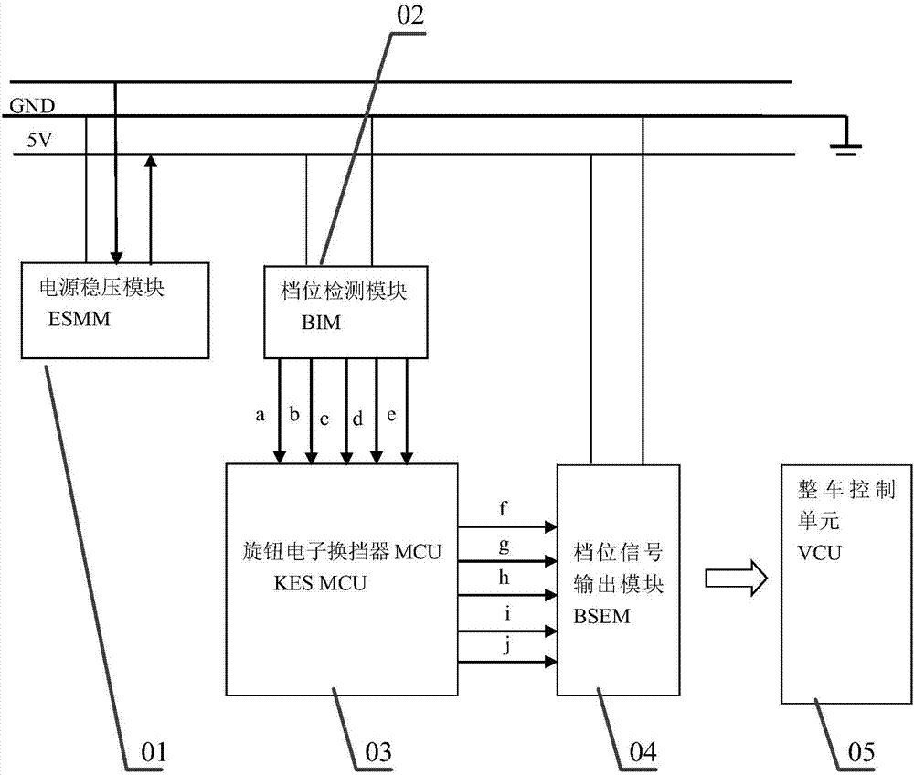
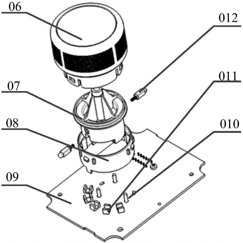
Technical field [0001] The invention relates to the field of automobile chassis transmission systems, in particular to a gear signal encoder. In addition, the present invention also relates to a rotary knob electronic shifter including the above-mentioned gear signal encoder. Background technique [0002] With the development of automotive electronic technology and the widespread application of automatic transmissions, electronic shifters are widely used in automobiles, including knob electronic shifters. [0003] The core components of the knob electronic shifter, please refer to figure 1 , Including power supply regulator module (ESMM) 01, gear detection module (BIM) 02, knob electronic shifter MCU (KES-MCU) 03, gear signal output module (BSEM) 04. Among them, ESMM01 converts the vehicle's 12V power supply to a 5V stable power supply, and then supplies power to other modules of the knob electronic shifter; BIM02 is responsible for detecting the knob position of the knob electron...

Claims


Application Information

Patent Timeline
Patent Type & Authority Applications(China)
IPC IPC(8): G01D5/347
Inventor 高翔王超张海成
Owner BEIJING CHANGAN AUTOMOBILE ENG TECH RES
Why Eureka
Try Eureka