
Low-frequency loading antenna

An antenna and low-frequency technology, applied in the field of radio transceivers, can solve the problems of large loss, deterioration of antenna performance, and low antenna radiation efficiency.

Inactive Publication Date: 2017-08-29
GUANGDONG KINGPOINT DATA SCI & TECH CO LTD
View PDF5 Cites 1 Cited by
  • Summary
  • Abstract
  • Description
  • Claims
  • Application Information

AI Technical Summary

Problems solved by technology

The large induced current will lead to a large loss, making the radiation efficiency of the antenna very low, and the gain will naturally become very low. Performance deterioration
[0004] At present, monopole antennas are mostly installed in some miniaturized terminals. The monopole antenna meets the miniaturization requirements, but in the low frequency (less than 100MHz) band, the bandwidth of the monopole antenna is very limited, which cannot meet the technical progress. needs

Method used

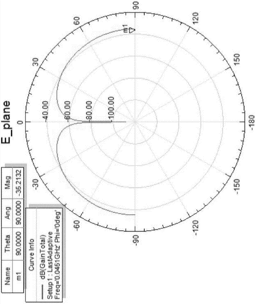
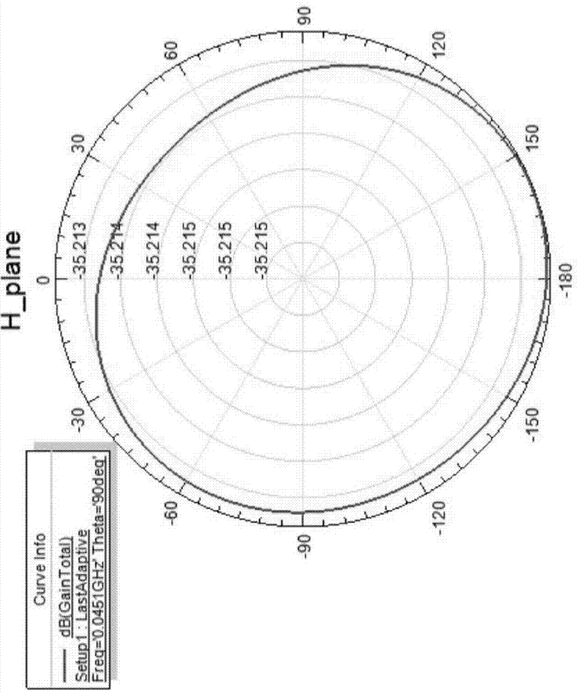
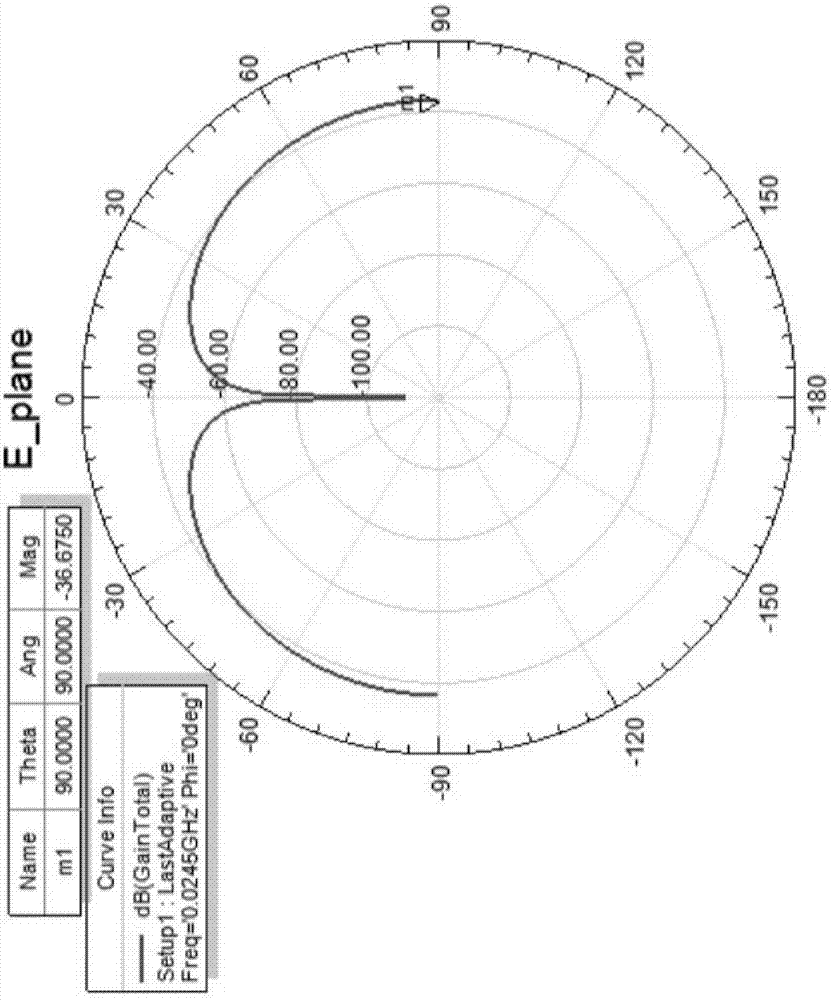

Image

  • Low-frequency loading antenna
  • Low-frequency loading antenna
  • Low-frequency loading antenna

Examples


Embodiment 1

[0028] A low frequency loading antenna comprising:

[0029] Monopole antenna, the feeder is connected to the monopole antenna, the length of the monopole antenna is 360mm, the radius is 7.5mm, and the distance between the radiation boundary and the antenna is 375mm;

[0030] a lumped loading part, the lumped loading part is connected in series with the monopole antenna;

[0031] Impedance transformer is used to realize that the impedance of the feed end of the monopole antenna is equal to the characteristic impedance of the feeder line. In this embodiment, the (needle) impedance transformer whose model is AT&T is selected for use;

[0032] Wherein, the lumped loading part includes an inductor and a resistor, which are connected in series with the monopole antenna. The parameters of the inductor and the resistor are 1.73 uH for the inductor and 2.12 kΩ for the resistor.

[0033] The reactance of the monopole antenna is capacitive, so if the inductance L and the resistance R ar...

Embodiment 2

[0041] Compared with Embodiment 1, the difference is that the parameters of the inductance and resistance are that the inductance is 102.70nH, the resistance is 420Ω, and a sleeve is also included, and the sleeve is covered on the top of the monopole antenna, and the top of the monopole antenna Connects to the inside of the sleeve.

[0042] According to the transmission line theory, a terminal short-circuit line with a total length not greater than a quarter of the wavelength can be used as an inductive load, and its equivalent reactance value can be calculated by the following formula:

[0043] wxya in =jZ 0 Tanβl

[0044] The sleeve can be regarded as a terminal short circuit, which is equivalent to an inductive load loaded on the top of the antenna. And because the monopole antenna is an antenna with capacitive impedance, the loading of the sleeve can just offset a certain capacitive reactance, thereby reducing the resonant frequency of the antenna and improving the impe...

Embodiment 3

[0046] Compared with Embodiment 1, the difference lies in that the inductance is an adjustable inductor, and the resistor is a sliding rheostat. In this way, when the monopole antenna is deformed within a certain range (such as being hit or broken), the present invention can still work normally by adjusting the parameters of the inductance and resistance.


PUM

PropertyMeasurementUnit
Inductanceaaaaaaaaaa
Resistanceaaaaaaaaaa
Inductanceaaaaaaaaaa

Abstract

The present invention belongs to the radio receiving-transmitting device field. Aiming at the technical problem of the bandwidth of a conventional monopole antenna in a low-frequency (being smaller than 100MHz) segment, the present invention concretely discloses a low-frequency loading antenna. The low-frequency loading antenna comprises: a monopole antenna which is connected with a feeder; a lumped loading portion being connected in series with the monopole antenna; and an impedance conversion portion configured to realize that the impedance of a feed terminal of the monopole antenna is equal to the characteristic impedance of the feeder, wherein the lumped loading portion comprises an inductor and a resistor, and the inductor and the resistor are connected in series with the monopole antenna.

Description

technical field [0001] The invention relates to the field of radio transceivers, in particular to a loading antenna. Background technique [0002] Radio equipment such as radar, television, navigation, and radio all rely on electromagnetic waves to transmit information, and the reception and transmission of electromagnetic waves are inseparable from antennas. In the low frequency (less than 100MHz) band, the working wavelength of the antenna is relatively long. Correspondingly, the size of the designed antenna will be relatively large, and it is difficult to install it on the working platform in a limited space. [0003] The antenna is the part of the communication system that is coupled with the free space. Only when its size is comparable to the wavelength of the electromagnetic wave transmitted in the free space, can it radiate and receive energy with high efficiency. In free space, if the operating frequency of the antenna is low, the corresponding operating wavelength ...

Claims


Application Information

Patent Timeline
IPC IPC(8): H01Q1/36H01Q1/50
CPCH01Q1/36H01Q1/50
Inventor 李青海侯大勇简宋全邹立斌
Owner GUANGDONG KINGPOINT DATA SCI & TECH CO LTD
Learn More