Form cutting tool

A technology for forming cutting and tooling, which is applied in the direction of manufacturing tools, turning equipment, metal processing equipment, etc., can solve the problems of decreased work efficiency, damaged cylindrical part 8, difficult to discharge, etc., and achieves the effect of improving work efficiency.

Active Publication Date: 2017-08-29
NSK LTD
View PDF8 Cites 1 Cited by
  • Summary
  • Abstract
  • Description
  • Claims
  • Application Information

AI Technical Summary

Problems solved by technology

Therefore, when the cutting oil is sprayed in the above-mentioned state, chips (swarf, slag) are pressed into one axial end side of the inner diameter side of the cylindrical portion 8 and are difficult to be discharged to the outside.
As a result, work for chip removal is required after machining, and work efficiency is reduced
In addition, if chips remain, the processed cylindrical portion 8 may be damaged.

Method used


Image

  • Form cutting tool
  • Form cutting tool
  • Form cutting tool

Examples


Embodiment Construction

[0075] [the first example of embodiment]

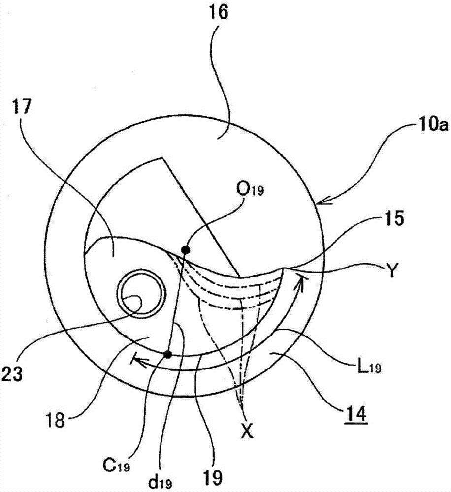
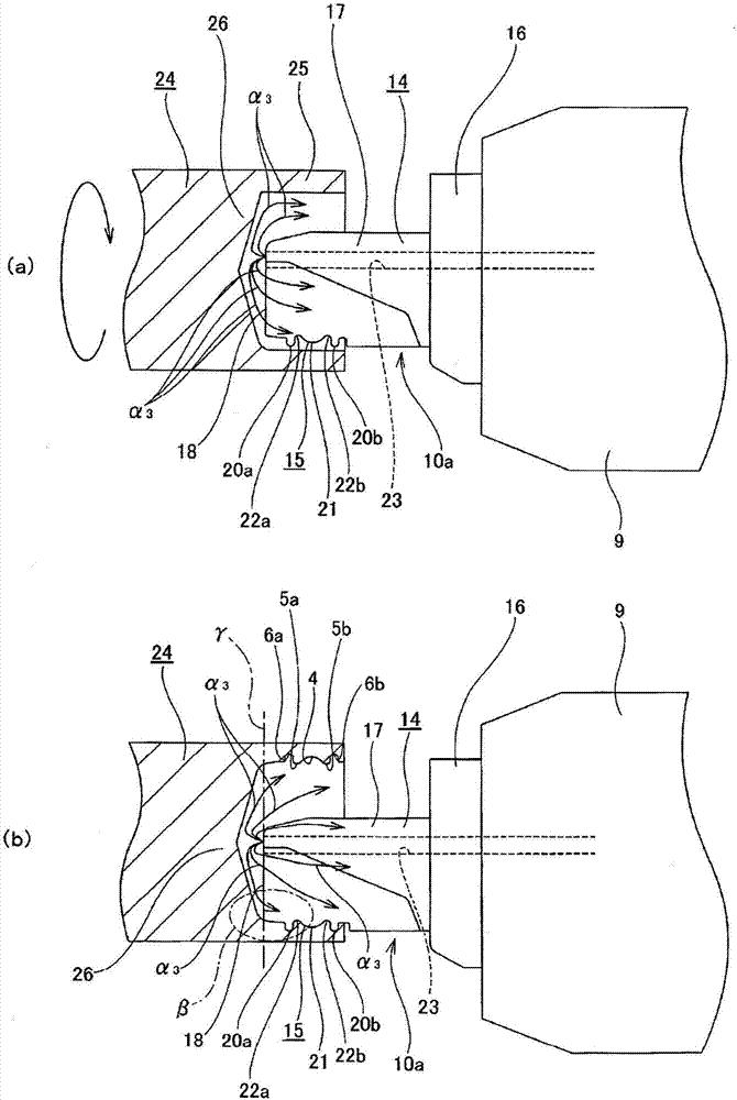
[0076] use figure 1 , 2 A first example of an embodiment of the present invention will be described. The shaped cutting tool 10a of this example is used for cutting to process the inner peripheral surface of the annular portion of the workpiece into a desired shape. Specifically, in for example constituting Figure 8 The inner peripheral surface of the outer ring 2 of the shown ball bearing 1 is used for cutting to form the outer ring raceway 4, a pair of shoulders 5a, 5b, and a pair of seal locking grooves 6a, 6b. Next, the structure of the shaped cutting tool 10a of this example will be described, and then a cutting method of assembling the shaped cutting tool 10a of this example in a machine tool (for example, a lathe, etc.) will be described.

[0077] The forming cutting tool 10a of this example is made of, for example, high-speed steel (SKH51, high-speed steel), cemented carbide, etc., and is used for cutting to form the oute...


PUM


Abstract

A form cutting tool (10a) is provided with a tool body (14) and a tooth section (15) formed on a circumferential portion near the tip of the leading end shaft section (17) of the tool body (14). An oiling passage (23), of which the opening at one end in the axial direction opens onto a flat surface (18) that is the leading end face of the leading end shaft section (17), is formed in the tool body (14). During cutting, cutting oil is supplied from the opening at the one end of the oiling passage (23) in the axial direction. As a result, it is possible to limit the occurrence of damage such as deposits or abrasion on the leading edge of the tooth section (15) and discharge of chips generated during machining to the outside of a circular member is facilitated.

Description

technical field [0001] The present invention relates to an improvement of a shaped cutting tool for cutting the inner peripheral surface of an annular member. Background technique [0002] As a radial ball bearing for supporting various rotating parts such as bearing parts of various rotating machinery, Patent Document 1 discloses Figure 8 Ball bearing 1 shown. The shape of the inner peripheral surface of the outer ring 2 or the inner ring 3 constituting such a ball bearing 1 is formed, for example, by cutting using a machine tool (lathe, etc.) equipped with a forming cutting tool. Below, refer to Figure 9 A cutting method for forming the outer ring raceway 4, the pair of shoulders 5a, 5b, and the pair of seal locking grooves 6a, 6b on the inner peripheral surface of the outer ring 2 will be briefly described. [0003] Such as Figure 9 Shown, its axial one end of cylindrical workpiece 7 ( Figure 9 The left end portion of the workpiece 7) is fixed to the main shaft (n...

Claims


Application Information

Patent Timeline
Patent Type & Authority Applications(China)
IPC IPC(8): B23B27/06B23B27/10
CPCB23B27/06B23B27/10B23Q11/10B23B2250/12
Inventor 安村昌纮
Owner NSK LTD
Why Eureka
Try Eureka