
Negative plate as well as preparation method and application thereof

A technology of negative electrode sheet and negative electrode, applied in the field of negative electrode sheet and its preparation, can solve the problems of unstable binder network, uneven distribution of conductive carbon, influence on safety, etc., achieve excellent cycle performance and rate performance, and simple preparation method Ease of operation and the effect of improving the overall electrical performance

Pending Publication Date: 2022-05-13
BATTERO TECH CORP LTD
View PDF7 Cites 0 Cited by
  • Summary
  • Abstract
  • Description
  • Claims
  • Application Information

AI Technical Summary

Problems solved by technology

However, the inherent semiconductor properties of silicon materials limit the fast charging ability of its batteries. In addition, the difference in electron transfer efficiency between the two materials during charging and discharging will cause uneven current distribution in the negative electrode sheet, resulting in a potential breakthrough in local areas. The lower limit of 0V produces lithium deposition, which reduces the fast charging performance of the power battery and affects safety
[0003] Due to the different surface tension of the two material particles, the silicon-doped graphite negative electrode sheet has different adsorption capabilities for conductive carbon and binder, so it is easy to have uneven distribution of conductive carbon and unstable binder network during mixing and homogenizing coating. , resulting in unsatisfactory battery rate performance; due to the difference in the electrochemical deintercalation potential of graphite material and silicon material, the two different active material materials will have the problem of deintercalating lithium successively, and the current distribution in the negative electrode sheet will be very uneven. , prone to local metal lithium deposition, which in turn affects the safety of the battery; therefore, how to have high-rate characteristics of the pole pieces obtained from two different active materials has become an urgent technical problem to be solved.

Method used


Image

  • Negative plate as well as preparation method and application thereof
  • Negative plate as well as preparation method and application thereof
  • Negative plate as well as preparation method and application thereof

Examples

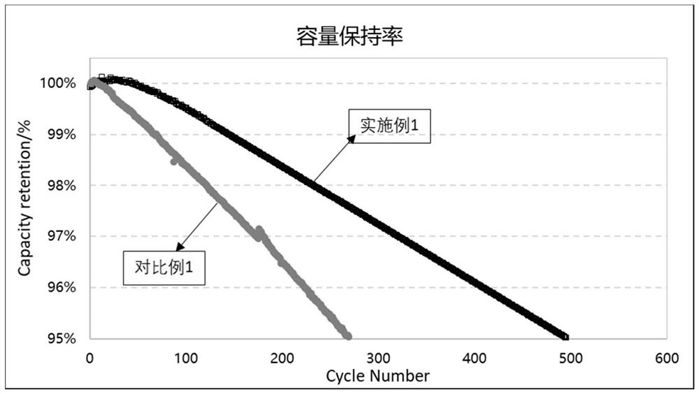
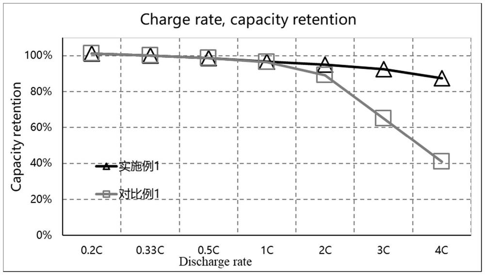

preparation example Construction

[0094] According to another aspect of the present invention, the present invention relates to the preparation method of the negative electrode piece, comprising the following steps:

[0095] The surface of the negative collector matrix is coated with at least one side of the carbon material slurry, after drying to obtain a negative collector with a carbon material layer; the first negative electrode slurry is coated on the surface of the carbon material layer away from the negative collector matrix, and the first negative active layer is given after drying; the first negative active layer is coated with a second negative electrode slurry on the surface away from the negative collector fluid matrix, and the second negative electrode active layer is obtained after drying;

[0096] The first negative electrode slurry comprises the first negative electrode active material, a first binder, a first conductive agent and a first solvent;

[0097] The second negative electrode slurry compri...

Embodiment 1

[0120] A method for preparing negative electrode sheets, comprising the following steps:

[0121] 1. Preparation of the first negative electrode active material and the second negative electrode active material

[0122] SiO was treated first under protective gas conditions to obtain a silicon-oxygen composite substrate, and then deposited the carbon source on the surface of the silicon-oxygen composite substrate by vapor deposition to form a carbon-coated silicon-oxygen material; the carbon-coated silicon-oxygen material and the nitrogen-containing substance were uniformly dispersed by aqueous solvent method, and then dried in N by blowing 2 The second heat treatment is carried out under atmosphere to form a modified silicon-based anode active material doped with N atoms; wherein the carbon source is acetylene; the temperature of the first heat treatment is 400 °C, and the insulation time is 60min; the temperature of vapor deposition is 800 °C, the time is 30min; the nitrogen-conta...

Embodiment 2

[0130] A method for preparing a negative electrode sheet, in addition to the preparation of the first negative electrode active material, the carbon-coated silicon oxygen material and the nitrogen-containing substance mass ratio is 1:2, other conditions are the same as Example 1.


PUM

PropertyMeasurementUnit
particle diameteraaaaaaaaaa
surface roughnessaaaaaaaaaa

Abstract

The invention relates to the technical field of batteries, in particular to a negative plate and a preparation method and application thereof. The negative electrode plate comprises a negative electrode current collector, a first negative electrode active layer and a second negative electrode active layer, the negative electrode current collector comprises a negative electrode current collector substrate and a carbon material layer arranged on at least one side surface of the negative electrode current collector substrate, a first negative electrode active layer is arranged on the surface, far away from the negative electrode current collector substrate, of the carbon material layer, and a second negative electrode active layer is arranged on the surface, far away from the negative electrode current collector, of the first negative electrode active layer; the first negative electrode active layer comprises a first negative electrode active material, a first binder and a first conductive agent, and the first negative electrode active material comprises a silicon-based negative electrode material doped with hetero atoms; the second negative electrode active layer comprises a second negative electrode active material and a second binder, and the second negative electrode active material comprises a hard carbon material doped with heteroatoms; the atoms comprise at least one of P, N, S, B and O. The negative plate has excellent fast charging performance.

Description

Technical field [0001] The present invention relates to the field of battery technology, in particular, to a negative electrode wafer and a preparation method and application thereof. Background [0002] In recent years, the sales of new energy vehicles have gradually increased, as a power source of lithium-ion batteries in all aspects of the performance is also increasingly demanding, of which, in order to solve the product "endurance and charging anxiety" problem, the new lithium-ion batteries need to have higher energy density and faster charging time. As the most mature negative electrode active material in the current industry, graphite's actual exertion capacity is basically close to the theoretical capacity, and it is difficult to meet the high energy density index. Based on the existing cathode main material and battery formulation system, the graphite mixed silicon-based anode helps to further improve the energy density of lithium-ion batteries, which can effectively so...

Claims


Application Information

Patent Timeline
Patent Type & Authority Applications(China)
IPC IPC(8): H01M4/133H01M4/36H01M4/38H01M4/62H01M10/04
CPCH01M4/628H01M4/366H01M4/133H01M4/386H01M10/04Y02P70/50
Inventor 廖星
Owner BATTERO TECH CORP LTD
Learn More