Refrigeration cycle device
A refrigeration cycle and refrigerant technology, used in refrigerators, refrigeration components, refrigeration and liquefaction, etc., can solve problems such as excessive oil and reduced refrigeration cycle efficiency
- Summary
- Abstract
- Description
- Claims
- Application Information
AI Technical Summary
Problems solved by technology
Method used
Image

Examples
no. 1 approach
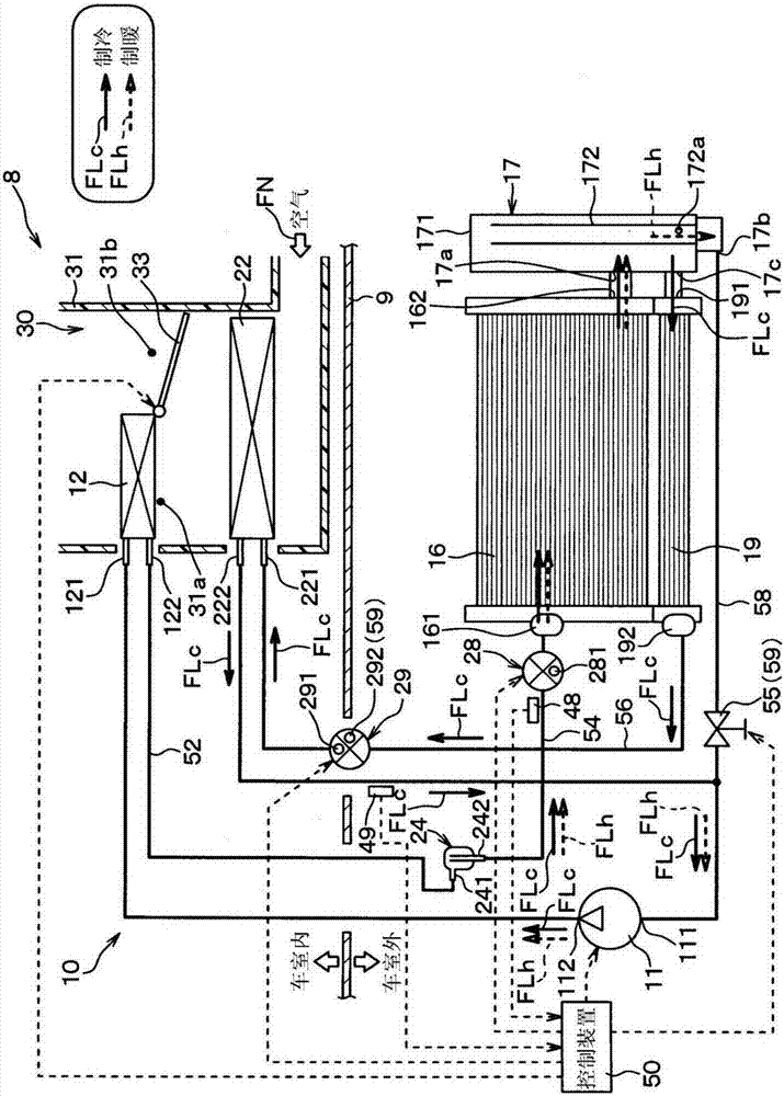
[0025] figure 1 It is an overall configuration diagram of the vehicle air conditioner 8 according to the present embodiment. This vehicle air conditioner 8 is mounted on a hybrid vehicle that obtains driving force for vehicle running from an internal combustion engine (engine) and a running electric motor. Such as figure 1 As shown, the vehicle air conditioner 8 has a vapor compression refrigeration cycle device 10 . The refrigeration cycle device 10 has a function of heating or cooling the blown air blown into the vehicle interior as a space to be air-conditioned in the vehicle air conditioner 8 .
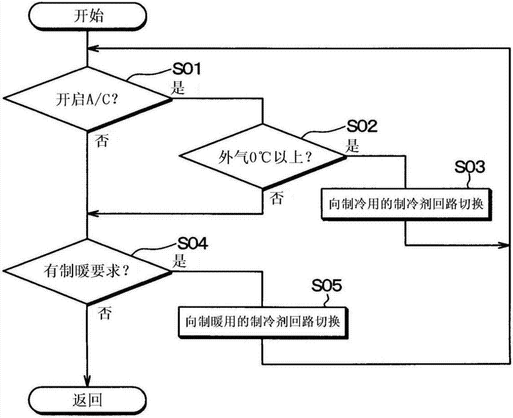
[0026] The refrigeration cycle device 10 is configured as a refrigerant circuit in a cooling mode (first mode) that cools the blown air to cool the vehicle interior and a heating mode that heats the blown air to heat the vehicle interior. (second mode) to switch between the refrigerant circuits.
[0027] In the refrigeration cycle device 10 , an HFC-based refrigerant (specific...
no. 2 approach
[0094] Next, a second embodiment of the present invention will be described. In this embodiment, the point which differs from the said 1st Embodiment is mainly demonstrated. In addition, explanations are omitted or simplified for parts that are the same as or equivalent to those in the foregoing embodiments. The same applies to the third and subsequent embodiments described later.
[0095] Figure 4 It is an overall configuration diagram of the vehicle air conditioner 8 of the present embodiment, which is the same as that of the first embodiment. figure 1 Quite a graph. Such as Figure 4 As shown, in this embodiment, a water-cooled capacitor 60 is provided instead of the condenser 12 of the first embodiment, and a heater core 62 is provided in the hot air passage 31 a of the indoor air conditioning unit 30 . Furthermore, a first decompression unit 28 is provided instead of the first expansion valve 28 of the first embodiment. In these respects, the present embodiment dif...
no. 3 approach
[0106] Next, a third embodiment of the present invention will be described. In this embodiment, the point which differs from the said 1st Embodiment is mainly demonstrated.
[0107] Figure 5 It is an overall configuration diagram of the vehicle air conditioner 8 of the present embodiment, which is the same as that of the first embodiment. figure 1 Quite a graph. Such as Figure 5 As shown, in this embodiment, the second expansion valve 29 of the first embodiment is replaced by the first temperature type expansion valve 74 and the first on-off valve 75, the first expansion valve 28 of the first embodiment is the same as that of the second embodiment The method is similarly replaced with the first decompression unit 28 . In addition, the refrigeration cycle device 10 has a second evaporator 76 , a second temperature expansion valve 78 , and a second on-off valve 79 . In these respects, the present embodiment differs from the first embodiment. In addition, a vehicle equipp...
PUM
 Abstract
Description
Claims
Application Information
 - R&D
- Intellectual Property
- Life Sciences
- Materials
- Tech Scout
- Unparalleled Data Quality
- Higher Quality Content
- 60% Fewer Hallucinations
Browse by: Latest US Patents, China's latest patents, Technical Efficacy Thesaurus, Application Domain, Technology Topic, Popular Technical Reports.
© 2025 PatSnap. All rights reserved.Legal|Privacy policy|Modern Slavery Act Transparency Statement|Sitemap|About US| Contact US: help@patsnap.com