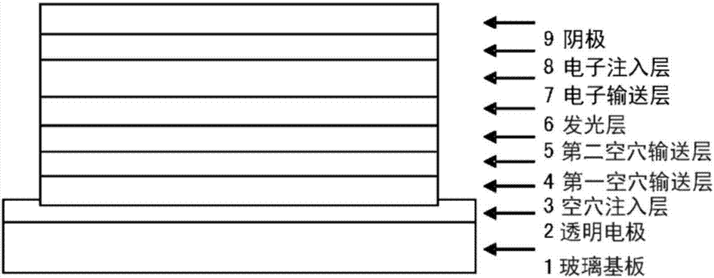
Organic electroluminescent element
一种电致发光器件、致发光的技术,应用在电固体器件、电气元件、发光材料等方向,能够解决驱动电压降低发光效率、结果不充分等问题,达到低驱动电压、良好效率、长寿命的效果
- Summary
- Abstract
- Description
- Claims
- Application Information
AI Technical Summary
Problems solved by technology
Method used
Image

Examples
Synthetic example 1
[0382]
[0383] Synthesis of 4,4"'-bis{(biphenyl-4-yl)-phenylamino}-(1,1':4',1":4",1"'-quaterphenyl);
[0384] Into a nitrogen purged reaction vessel was added
[0385]
[0386] And nitrogen gas was passed therethrough for 1 hour. Then, 1.1 g of tetrakis(triphenylphosphine)palladium was added, followed by heating, and stirring was performed at 72° C. for 10 hours. A total of 60 mL of methanol was added after cooling to room temperature. The precipitated solid was collected by filtration and washed with 100 mL of a mixed solution of methanol / water (5 / 1, v / v). Next, 100 mL of 1,2-dichlorobenzene was added and dissolved under heating. Insolubles were removed by filtration, followed by gradual cooling and addition of 200 mL of methanol. The precipitated crude product was collected by filtration. The crude product was washed with 100 mL of methanol at reflux. As a result, 11.8g (yield 81%) of 4,4"'-bis{(biphenyl-4-yl)-phenylamino}-(1,1':4',1":4",1" was obtained '-quater...
Synthetic example 2
[0395]
[0396] 4,4""-bis{(biphenyl-4-yl)-phenylamino}-(1,1':4',1":4",1"':4"',1""-kink phenyl) synthesis;
[0397] Into a nitrogen purged reaction vessel was added
[0398]
[0399] And nitrogen gas was passed therethrough for 1 hour. Then, 1.0 g of tetrakis(triphenylphosphine)palladium was added, followed by heating, and stirring was performed at 72° C. for 18 hours. After cooling to room temperature, a total of 60 mL of methanol was added. The precipitated solid was collected by filtration and washed with 100 mL of a mixed solution of methanol / water (5 / 1, v / v). Next, 100 mL of 1,2-dichlorobenzene was added and dissolved under heating. Insolubles were removed by filtration, followed by gradual cooling and addition of 200 mL of methanol. The precipitated crude product was collected by filtration. The crude product was washed with 100 mL of methanol at reflux. As a result, 9.8 g (yield 66%) of 4,4""-bis{(biphenyl-4-yl)-phenylamino}-(1,1':4',1":4",1 "':4"',1""-kinke...
Synthetic example 3
[0408]
[0409] Synthesis of 4,4"'-bis{(biphenyl-4-yl)-phenylamino}-(1,1':3',1":3",1"'-quaterphenyl);
[0410] The reaction was performed on the same conditions as in Synthesis Example 1 except that 3,3'-dibromobiphenyl was used instead of 4,4'-diiodobiphenyl.
[0411] As a result, 16.2 g (yield 91%) of 4,4"'-bis{(biphenyl-4-yl)-phenylamino}-(1,1':3',1":3",1 "'-quaterphenyl) (compound 1-11) light yellow powder.
[0412]
[0413] The structure of the resulting pale yellow powder was identified using NMR. exist 1 H-NMR (CDCl 3 ), the following 44 hydrogen signals were detected.
[0414] δ(ppm)=7.87(2H)
[0415] 7.48-7.66(18H)
[0416] 7.39-7.48(4H)
[0417] 7.29-7.39(6H)
[0418] 7.18-7.26(12H)
[0419] 7.08(2H)
PUM
| Property | Measurement | Unit |
|---|---|---|
| glass transition temperature | aaaaa | aaaaa |
| glass transition temperature | aaaaa | aaaaa |
| fluorescence quantum yield | aaaaa | aaaaa |
Abstract
Description
Claims
Application Information
 - R&D
- Intellectual Property
- Life Sciences
- Materials
- Tech Scout
- Unparalleled Data Quality
- Higher Quality Content
- 60% Fewer Hallucinations
Browse by: Latest US Patents, China's latest patents, Technical Efficacy Thesaurus, Application Domain, Technology Topic, Popular Technical Reports.
© 2025 PatSnap. All rights reserved.Legal|Privacy policy|Modern Slavery Act Transparency Statement|Sitemap|About US| Contact US: help@patsnap.com