Self-swinging stirrer
A mixer and self-biasing technology, which is applied to mixers with rotating stirring devices, mixers, dissolving, etc., can solve the problems of affecting the mixing efficiency, large resistance of the stirring paddle, safety accidents, etc., to speed up the feedback speed and ease the mixing operation , the effect of reducing the contact time
- Summary
- Abstract
- Description
- Claims
- Application Information
AI Technical Summary
Problems solved by technology
Method used
Image
Examples
Embodiment 1
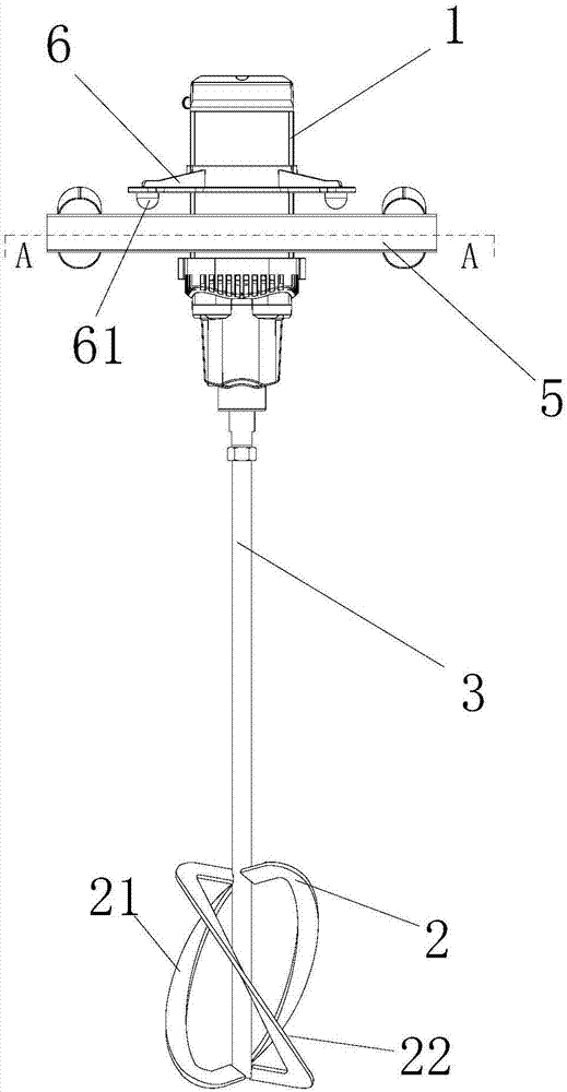
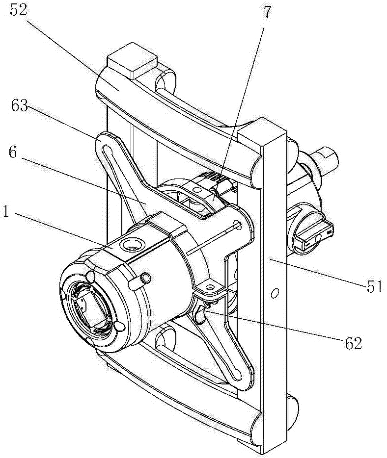
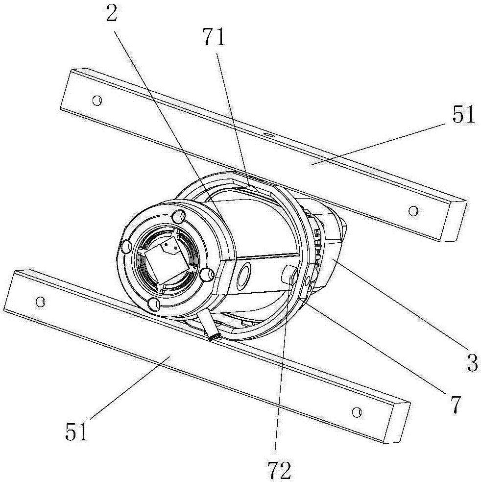
[0025] Example 1 as Figure 1 to Figure 6 As shown, the self-deflecting mixer of this embodiment includes: an operating handle 5, a stirring rod 3, and a body 1; the bottom end of the body 1 is connected to the stirring rod 3 for providing rotational power to the stirring rod 3, The bottom end of the asymmetrical paddle 2 is connected, and the paddle 2 includes two C-shaped paddles 21 and one S-shaped paddle 22, and the two ends of the C-shaped paddle 21 are fixedly connected with the stirring rod 3, and the S-shaped paddle The two ends of 22 are fixedly connected with the stirring rod 3, and the weight difference on both sides of the stirring rod 3 makes the center of gravity of the stirring paddle 2 not coincide with the axis of the stirring rod 3, so as to ensure that the stirring rod 3 is tilted when it is stationary.
[0026] The operating handle 5 is a frame-type operating handle composed of two horizontal braces 51 and two vertical braces 52. The fuselage 1 passes throu...
Embodiment 2
[0030] On the basis of embodiment 1, the difference between this embodiment and embodiment 1 is that, as Figure 8 As shown, a limit spring 65 (replacing the hemispherical contact portion 61 in Embodiment 1) is vertically provided on the lower end surface of each limit claw 63, and the bottom end of the limit spring 65 is connected with the upper end of the frame-type operating handle cross brace 51. The end faces are fixedly connected, when the fuselage 1 drives the limit clamp 6 to deflect, as Figure 9 As shown, the limit spring 65 on one side of the fuselage is compressed to produce elastic deformation, and the limit spring 65 on the other side is stretched to produce elastic deformation. Finally, the fuselage 1 deflects in the opposite direction under the action of the limit springs 65 on both sides of the fuselage 1 , thereby changing the deflection direction of the fuselage 1 .
PUM
 Abstract
Description
Claims
Application Information
 - R&D
- Intellectual Property
- Life Sciences
- Materials
- Tech Scout
- Unparalleled Data Quality
- Higher Quality Content
- 60% Fewer Hallucinations
Browse by: Latest US Patents, China's latest patents, Technical Efficacy Thesaurus, Application Domain, Technology Topic, Popular Technical Reports.
© 2025 PatSnap. All rights reserved.Legal|Privacy policy|Modern Slavery Act Transparency Statement|Sitemap|About US| Contact US: help@patsnap.com


