Novel oil-saving spindle with dynamic self-rotating airflow gap sealing

A technology of airflow gap and rotating airflow, which is applied in the direction of textiles and papermaking, can solve the problems of unsatisfactory fuel saving effect and inability to implement effective sealing effect, and achieve the effect of enhancing dynamic sealing effect and avoiding oil mist leakage

Pending Publication Date: 2017-09-01
HENAN NO 2 TEXTILE MACHINERY
View PDF10 Cites 3 Cited by
  • Summary
  • Abstract
  • Description
  • Claims
  • Application Information

AI Technical Summary

Problems solved by technology

[0014] From the point of view of the structure design of a fuel-saving spindle with patented technology, the sealing groove on the bearing sealing cover is a concave annular groove in the inner hole, and no other sealing medium is installed, and the bearing sealing cover is relatively close to the spindle rod. Large gap fit, the spindle bar itself runs at high speed, and there is no mechanism to prevent the lubricating oil from climbing up the surface of the spindle bar at the stationary bearing seal cover relative to the spindle foot, so this structure cannot implement effective sealing effect, and the lubricating oil will still flow along the upper bearing. The surface of the spindle bar climbs up and penetrates the outer space of the spindle
In essence, the upper bearing, bearing sealing cover, sealing groove, and the spindle rod of the high-speed rotating part are still open structures, and no sealing technology is used, and the actual fuel saving effect is not ideal

Method used


Image

  • Novel oil-saving spindle with dynamic self-rotating airflow gap sealing
  • Novel oil-saving spindle with dynamic self-rotating airflow gap sealing
  • Novel oil-saving spindle with dynamic self-rotating airflow gap sealing

Examples


Embodiment Construction

[0035] The technical solutions in the embodiments of the present invention will be further described below in conjunction with the drawings in the embodiments of the present invention.

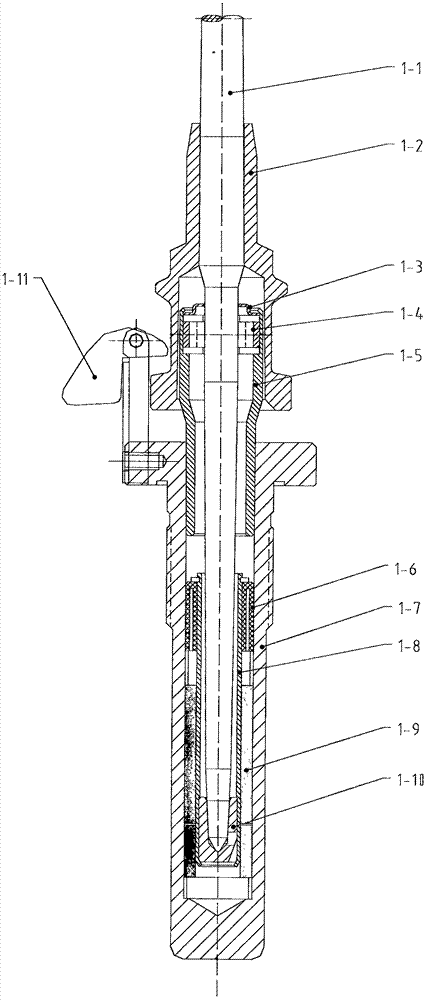
[0036] Figure 1 It is a structural diagram of a separate spindle in the prior art, consisting of a spindle bar 1-1, a spindle disc 1-2, a bearing washer 1-3, an upper bearing 1-4, an upper bearing seat 1-5, a nylon ring 1-6, a spindle It consists of feet 1-7, center sleeve 1-8, vibration-absorbing coil spring 1-9, ingot bottom 1-10, and ingot hook joint 1-11.

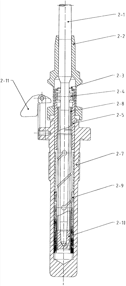
[0037] Figure II It is a structural diagram of an elastic tubular pointed spindle in the prior art, consisting of a spindle rod 2-1, a spindle disc 2-2, a bearing washer 2-3, an upper bearing 2-4, an upper bearing seat 2-5, and a spindle foot 2- 7. It consists of elastic tube 2-8, shock-absorbing coil spring 2-9, ingot bottom 2-10, and ingot hook joint 2-11.

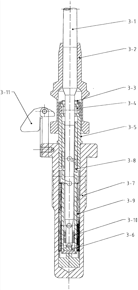
[0038] Figure three It is a structural diagram of an elastic tubular f...


PUM


Abstract

The invention discloses a novel oil-saving spindle with dynamic self-rotating airflow gap sealing, and belongs to the textile machinery industry. Lubricating oil is sealed into an inner cavity of a spindle by dynamic self-rotating airflow gap sealing technology. The novel oil-saving spindle is composed of a spindle rod, a spindle disk, an air gap sealing groove, a rotary airflow bearing sealing cover, a polymer sealing ring, a sealing groove, an upper bearing, an upper bearing seat, a gasket, a spindle foot, an elastic tube, a vibration absorbing coil spring, a spindle bottom, a spindle hook joint part and an axial spring. Spindle oil non-normal loss results from the spindle structure design. In the prior art, the upper bearing of the spindle is open type oil mist thin film lubricating, and the spindle oil evaporates into the atmosphere in an oil mist mode to cause loss. The unique dynamic self-rotating airflow gap sealing technology is used to solve the existing technical shortcomings, and the novel oil-saving spindle is applicable to the transformation of current different spindle oil-saving technologies. The spindle oil filling cycle extends from 3 months to 12-24 months. The operation cost of equipment is reduced; the labor intensity is reduced; the employment of enterprises is reduced; the workload of a spindle oil filling machine is reduced; the needs of spindle oil saving and the like are met.

Description

technical field [0001] The invention belongs to the manufacturing industry of special parts of textile machinery. The dynamic autorotation airflow gap sealing technology is applied to the high-speed rotating operation of the spindle, and the dynamic autorotation airflow gap sealing is implemented on the spindle lubricating oil, and the spindle lubricating oil is sealed by the dynamic autorotation airflow gap sealing technology. It is sealed in the inner cavity of the spindle, thereby prolonging the refueling cycle and service life of the spindle. It is a new type of fuel-saving spindle with a dynamic self-rotating airflow gap seal. Background technique [0002] Spindle is a special part of textile machinery that rotates at high speed on the spinning frame of the textile industry. There are hundreds of millions of spindles in operation across the country. It is the pursuit of textile machinery manufacturing and textile enterprises to develop and adopt spindles that are adapta...

Claims


Application Information

Patent Timeline
Patent Type & Authority Applications(China)
IPC IPC(8): D01H7/04D01H7/20D01H7/12
CPCD01H7/047D01H7/12D01H7/20
Inventor 缪山林曹秀成曹旭张新文王国辉
Owner HENAN NO 2 TEXTILE MACHINERY
Why Eureka
Try Eureka