Switching valve with built-in circulation channel structure

A flow channel, switching valve technology, applied in the application field of valve structure, to reduce wear and improve overall performance and quality

Pending Publication Date: 2017-09-01
BEIJING LIYUAN INSTR CO LTD
View PDF10 Cites 0 Cited by
  • Summary
  • Abstract
  • Description
  • Claims
  • Application Information

AI Technical Summary

Problems solved by technology

[0016] In order to overcome the problems existing in the current high-pressure switching valve, the present invention provides a method of changing the arc-shaped groove flow path structure on the rotor in the prior art of the switching valve into a hole structure with a built-in flow channel, thereby adjusting the flow path on the surface of the rotor To the interior o...

Method used


Image

  • Switching valve with built-in circulation channel structure
  • Switching valve with built-in circulation channel structure
  • Switching valve with built-in circulation channel structure

Examples


Embodiment Construction

[0037] The present invention will be further described below in conjunction with the accompanying drawings. The expressions and terminology about mechanical dimensions and positions in the following description process are all for the purpose of describing the patent of the present invention clearly, so they cannot be used as restrictions on the patent of the present invention. This means that as long as there is no innovative design condition, only changes or adjustments in position, size, processing method and shape all belong to the protection scope of the patent of the present invention.

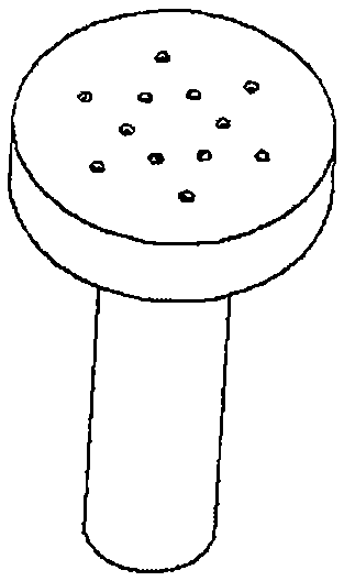
[0038] figure 2 It is a schematic diagram of the rotor structure of the switching valve in the prior art, which is composed of concentric arc grooves. If it is a six-way switching valve, there are three arc grooves, and if it is a 12-way valve, there are six arc grooves.

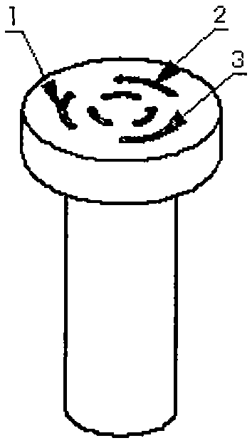
[0039] image 3 It is a schematic diagram of the patented rotor of the present invention. In order to express mo...


PUM


Abstract

The invention discloses a valve structure with a built-in circulation channel. The switching valve includes a 3-channel to multi-channel high-pressure liquid or gas valve with the structure. Specifically, the valve structure comprises: a valve stator connected to a pipeline and a valve rotor with the built-in circulation channel structure. The stator structure has no difference with the prior art, however the rotor has fundamental change compared with the prior art. For the rotor, the traditional surface arc-shaped groove is successfully changed into an inclined hole of the built-in circulation channel, thus fundamentally solving the key problems of end face wear caused by valve stator and valve rotor asymmetry, end face pressure nonuniformity brought about to rotation when the valve works under pressure and no pressure, and easy liquid leakage of an arc-shaped groove structure, etc.

Description

[0001] Technical field: [0002] The present invention generally relates to a novel valve structure, which can be used for gas and liquid valve structures, and particularly relates to the application of the valve structure of high-pressure sampling valves in chromatographic analysis instruments. [0003] Background technique: [0004] Liquid or gas switching valves are widely used in various fields, and play a very important role in chemical analysis instruments, especially chromatographic chemical analysis instruments. Switching valves are used in chromatographic analysis instruments to send the detected samples quantitatively through the switching of the valves for sample analysis. With the development of chromatography, the pressure of the system is getting higher and higher, especially the ultra-high pressure chromatography puts forward higher requirements for the switching valve, and at the same time, the long-term durability of the valve must be ensured, because the switc...

Claims


Application Information

Patent Timeline
IPC IPC(8): G01N30/20
CPCG01N30/20G01N2030/202
Inventor 昝保真昝军赏珩
Owner BEIJING LIYUAN INSTR CO LTD
Why Eureka
Try Eureka