
Virtual synchronous generator parameter design method

A technology of virtual synchronization and parameter design, which is applied in the direction of electrical components, circuit devices, AC network circuits, etc., can solve problems that are difficult to simultaneously balance power current characteristics and damping characteristics, simulate synchronous generators with large virtual moment of inertia, droop coefficient and The damping coefficient cannot be independently designed and adjusted, etc.

Active Publication Date: 2017-09-01
合肥庐阳科技创新集团有限公司
View PDF3 Cites 12 Cited by
  • Summary
  • Abstract
  • Description
  • Claims
  • Application Information

AI Technical Summary

Problems solved by technology

This paper proposes a design method for the decoupling of active and reactive power outer loop parameters. The proposed method can quickly and accurately obtain the design parameters without trial and error, but the virtual moment of inertia of the simulated synchronous generator is large and sacrifices Dynamic Response of Virtual Synchronous Generator
[0008] In short, the droop coefficient and damping coefficient of the existing virtual synchronous generator parameter design method cannot be independently designed and adjusted, and it is difficult to take into account the power current sharing characteristics and damping characteristics at the same time, and the parameter design method of simulating the parameters of the synchronous generator is not conducive to the use of power electronic conversion. The advantages of flexible and fast inverter control, and the characteristics of the AC side filter parameters of the virtual synchronous generator under digital control delay are rarely discussed, and the design method is complicated

Method used


Image

  • Virtual synchronous generator parameter design method
  • Virtual synchronous generator parameter design method
  • Virtual synchronous generator parameter design method

Examples


Embodiment Construction

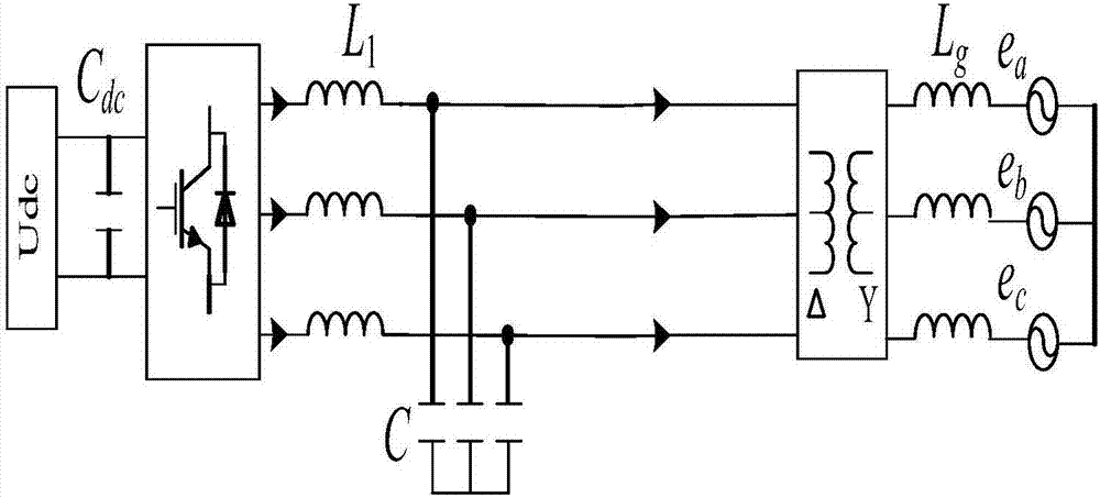
[0062] figure 1 is the topology structure of the virtual synchronous generator in the embodiment of the present invention. Including DC source U dc , DC side energy storage capacitor C dc , three-phase half-bridge inverter circuit, LC filter, DC side energy storage capacitor C dc in parallel with the DC source U dc Both ends of the DC source U dc The two power output terminals of the three-phase half-bridge inverter circuit are respectively connected to the two input terminals of the three-phase half-bridge inverter circuit, and the three-phase output terminals of the three-phase half-bridge inverter circuit are connected to the three-phase input terminals of the LC filter one by one. The three-phase output terminals of the transformer are respectively connected to the delta side of the Dyn11 transformer, and the star side of the transformer is connected to the three-phase grid e a 、e b 、e c connected, L g is the inductance corresponding to the inductive reactance of t...


PUM


Abstract

The invention discloses a virtual synchronous generator parameter design method. The method comprises the following steps: to begin with, calculating delay time of digital control of a virtual synchronous generator; obtaining an LC resonant frequency stability domain based on stability margin according to an open-loop transfer function of a control loop and generalized Nyquist stability criterion; calculating resonant frequency through a weighted geometric mean calculation method; for outer ring parameters, parameters are designed independently through a droop coefficient and damping coefficient independent control method; and through combination of advantages of flexible control and fast dynamic response of a power electronic converter and adaptive droop and big inertia and the like of a synchronous generator, a quasi-synchronous generator outer-ring parameter design method is provided. The method saves tedious repeated trial and error steps, and the calculating method is simple and visual.

Description

technical field [0001] The invention relates to a parameter design method of a virtual synchronous generator, in particular to a parameter design method based on the characteristics of a quasi-synchronous generator. Background technique [0002] In virtual synchronous generator control, virtual synchronous generator (Virtual Synchronous Generator-VSG) technology shows excellent control performance with its common voltage source control mode combined with off-grid. Several key control objectives of VSG-based virtual synchronous generators are: (1) During grid-connected operation, virtual inertia, virtual damping, virtual impedance and droop characteristics can be provided to the grid to support grid frequency and voltage changes and maintain large grid stability , and maintain the current sharing characteristics between virtual synchronous generators; (2) When running off-grid, it needs to provide higher power quality to the load. In addition, the VSG needs to operate in bot...

Claims


Application Information

Patent Timeline
IPC IPC(8): H02J3/00
CPCH02J3/00H02J2203/20
Inventor 刘芳王梦王付胜杨淑英张杰张兴
Owner 合肥庐阳科技创新集团有限公司
Learn More