Atomic oscillator

a technology of atomic oscillators and oscillators, which is applied in the direction of oscillator generators, pulse automatic control, masers, etc., can solve the problems of increasing the size of oscillator circuits, increasing the jitter at the output of rf signals, and conventional circuit arrangement is not optimal in noise and noise. , to achieve the effect of improving frequency stability

Inactive Publication Date: 2005-03-31
FUJITSU LTD
View PDF4 Cites 31 Cited by
  • Summary
  • Abstract
  • Description
  • Claims
  • Application Information

AI Technical Summary

Benefits of technology

In view of the foregoing, it is an object of the present invention to provide a compact, high-quality atomic oscillator with improved frequency stability.

Problems solved by technology

The use of multiple synthesizers, however, increases the size of oscillator circuits.
This conventional circuit arrangement is not optimal in terms of noise and spurious components that could be contained in the RF signal, as will be discussed below.
The problem with the conventional oscillator 200 is that the VCXO jitter is multiplied by the frequency multiplier 202d, together with the oscillation signal, resulting in a larger amount of jitter observed at the RF signal output.
In addition, spurious components inherent in the DDS output could be another source of noise.
For those reasons, the RF signal produced in the conventional oscillator 200 is contaminated with a considerable amount of noise, which causes degradation of signal-to-noise (SIN) ratio in detecting resonance of the atomic resonator 203.
This problem holds also for the oscillator disclosed in the Japanese unexamined patent publication No. 3-235422 mentioned above.
This means that the mixer receives an oscillation signal with increased jitter, which results in a large phase noise.
The problem here is that the curve of output frequency versus C-field strength is not linear.
This non-linearity makes it difficult for users to control the output frequency of an atomic oscillator.
Another issue to consider is a drift of output frequency.
Conventional oscillators, including those shown in FIGS. 18 and 19 and Japanese unexamined patent publication No. 3-235422, lack the function of controlling such parameters, thus failing to avoid degradation of frequency stability.

Method used


Image

  • Atomic oscillator
  • Atomic oscillator
  • Atomic oscillator

Examples


Embodiment Construction

Preferred embodiments of the present invention will be described below with reference to the accompanying drawings, wherein like reference numerals refer to like elements throughout.

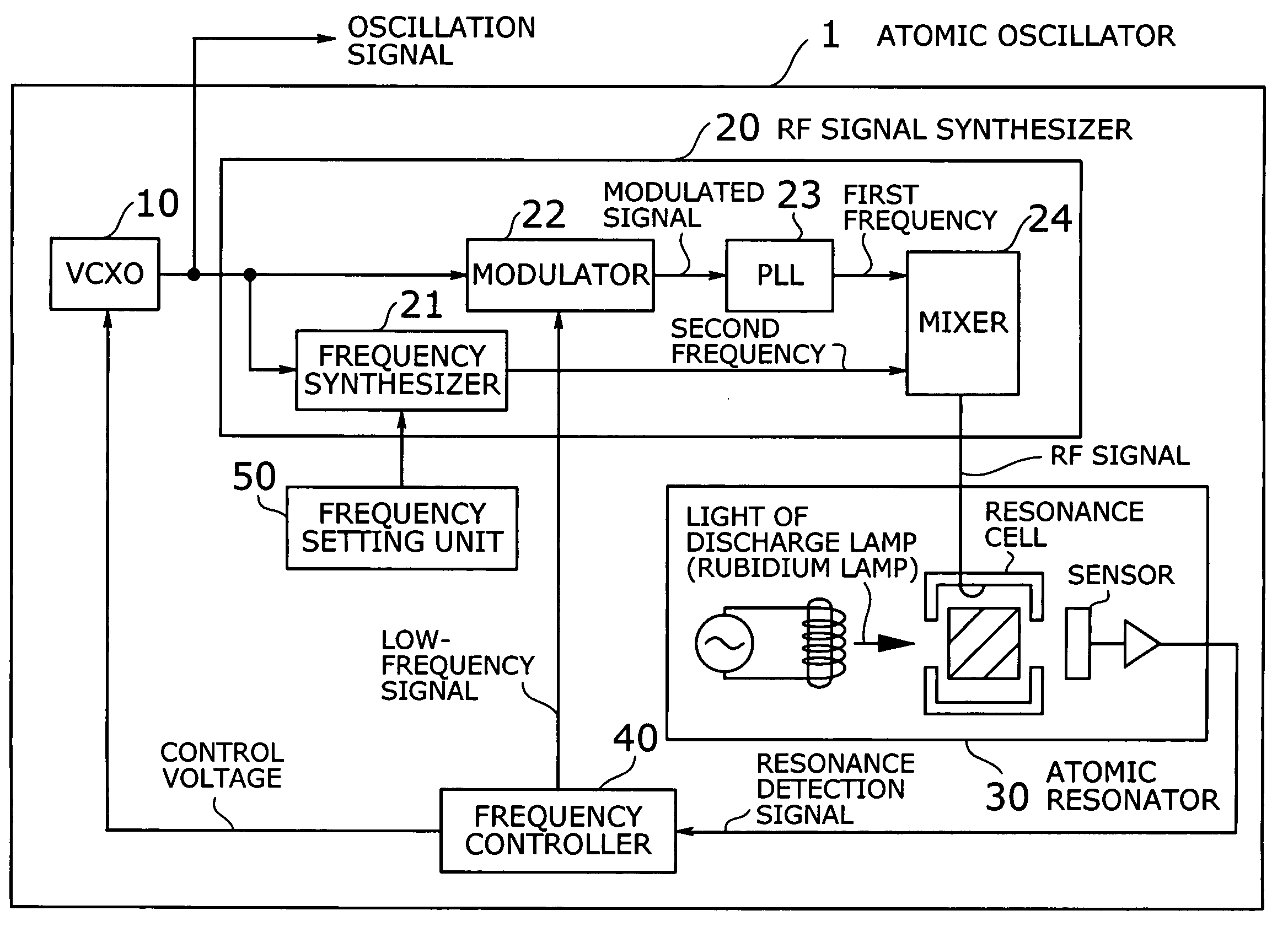
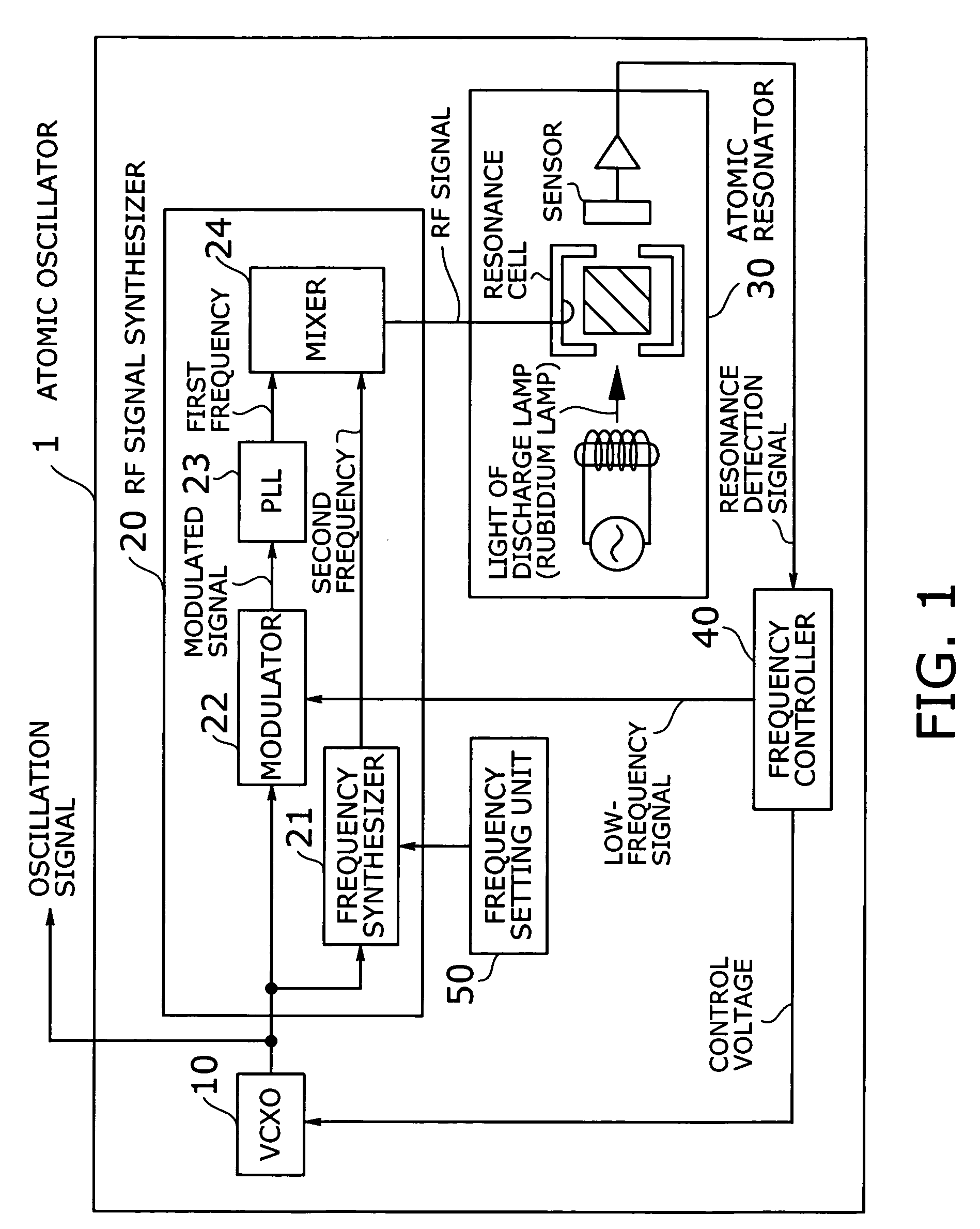
FIG. 1 is a conceptual view of an atomic oscillator according to the present invention. This atomic oscillator 1 produces a clock signal whose frequency is determined by the energy transitions of Rubidium atoms. The atomic oscillator 1 comprises the following functional blocks: a voltage-controlled crystal oscillator (VCXO) 10, an RF signal synthesizer 20, an atomic resonator 30, a frequency controller 40, and a frequency setting unit 50.

With a given control voltage, the VCXO 10 produces an oscillation signal with a frequency as stable as the atomic resonance frequency for use in external devices. This oscillation signal is also supplied to an RF signal synthesizer 20, which is composed of a frequency synthesizer 21, a modulator 22, a PLL 23, and a mixer 24. Inside the RF signal synthesizer 20, the m...


PUM


Abstract

A compact atomic oscillator with improved frequency stability. A voltage-controlled oscillator generates an oscillation signal based on a given control voltage, and a modulator modulates it with a low-frequency signal. A phase-locked loop (PLL) upconverts the modulated oscillation signal directly to a first frequency in atomic resonance frequency band. The first frequency is an integer multiple of the oscillation signal. A frequency synthesizer produces a second frequency specified by a frequency setting unit, and a mixer combines the first and second frequencies to produce an RF signal for driving an atomic resonator. The amount of discharge lamp light passing through the atomic resonator depends on the difference between RF signal frequency and atomic resonance frequency. This quantity is measured as a resonance detection signal, and a frequency controller applies it to synchronous detection to produce a control voltage for the voltage-control oscillator.

Description

BACKGROUND OF THE INVENTION 1. Field of the Invention The present invention relates to an atomic oscillator, and particularly to an atomic oscillator whose resonance frequency derives from energy transitions of rubidium atoms. 2. Description of the Related Art Rubidium atomic oscillators provide a constant frequency output by taking advantage of a highly stable resonance frequency of rubidium (Rb) atoms. Because of their extremely high frequency stability, rubidium oscillators are widely used as a frequency standard for television broadcast services and also as a high-accuracy timing source for digital synchronous networks and mobile communications systems. A high degree of accuracy is not the only thing that the customers demand; the market always seeks more compact and less costly solutions for rubidium frequency standards. FIG. 18 shows a typical basic structure of an existing rubidium atomic oscillator. The illustrated rubidium atomic oscillator 100 is formed from a voltage-...

Claims


Application Information

Patent Timeline
Patent Type & Authority Applications(United States)
IPC IPC(8): H03L7/26
CPCH03L7/26
Inventor ATSUMI, KENMATSUURA, HIDEYUKIKIKUCHI, AKIRA
Owner FUJITSU LTD
Why Eureka
Try Eureka