Annular matrix type rapid charging system with plurality of parallel power segments and control method thereof

A fast charging, multi-power technology, applied in charging stations, electric vehicle charging technology, current collectors, etc., can solve the problems that the charging pile cannot be called, and the output power of the charging pile cannot meet the needs of electric vehicles, so as to reduce the cost investment and ensure The effect of charging speed

Active Publication Date: 2017-09-01
EAST GRP CO LTD
View PDF5 Cites 7 Cited by
  • Summary
  • Abstract
  • Description
  • Claims
  • Application Information

AI Technical Summary

Problems solved by technology

There is a charging system in the charging station. The charging system is responsible for the conversion of electric energy and the distribution of power to each charging pile. The power module in the electric energy system is responsible for the conversion of AC and DC. The power distribution scheme of the existing charging system can be based on the power output of the charging pile. Requirements to adjust the number of power modules connected to the charging pile, limited by the existing power module deployment method, there are situations where there are sufficient idle power modules, but the output power of the charging pile cannot meet the needs of electric vehicles. The reason is that in the existing In the solution, a single charging pile can only call the power module under a specific connection relationship. For power modules with no specific connection relationship, even if it is in an idle state, the charging pile cannot be called

Method used


Image

  • Annular matrix type rapid charging system with plurality of parallel power segments and control method thereof
  • Annular matrix type rapid charging system with plurality of parallel power segments and control method thereof
  • Annular matrix type rapid charging system with plurality of parallel power segments and control method thereof

Examples


Embodiment Construction

[0028] In order to facilitate the understanding of the present invention, the following will describe the present invention more fully. However, the present invention can be embodied in many different forms and is not limited to the embodiments described herein. On the contrary, these embodiments are provided to make the understanding of the disclosure of the present invention more thorough and comprehensive.

[0029] Unless otherwise defined, all technical and scientific terms used herein have the same meaning as commonly understood by one of ordinary skill in the technical field of the invention. The terms used herein in the description of the present invention are for the purpose of describing specific embodiments only, and are not intended to limit the present invention.

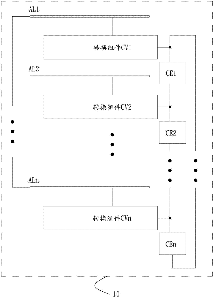
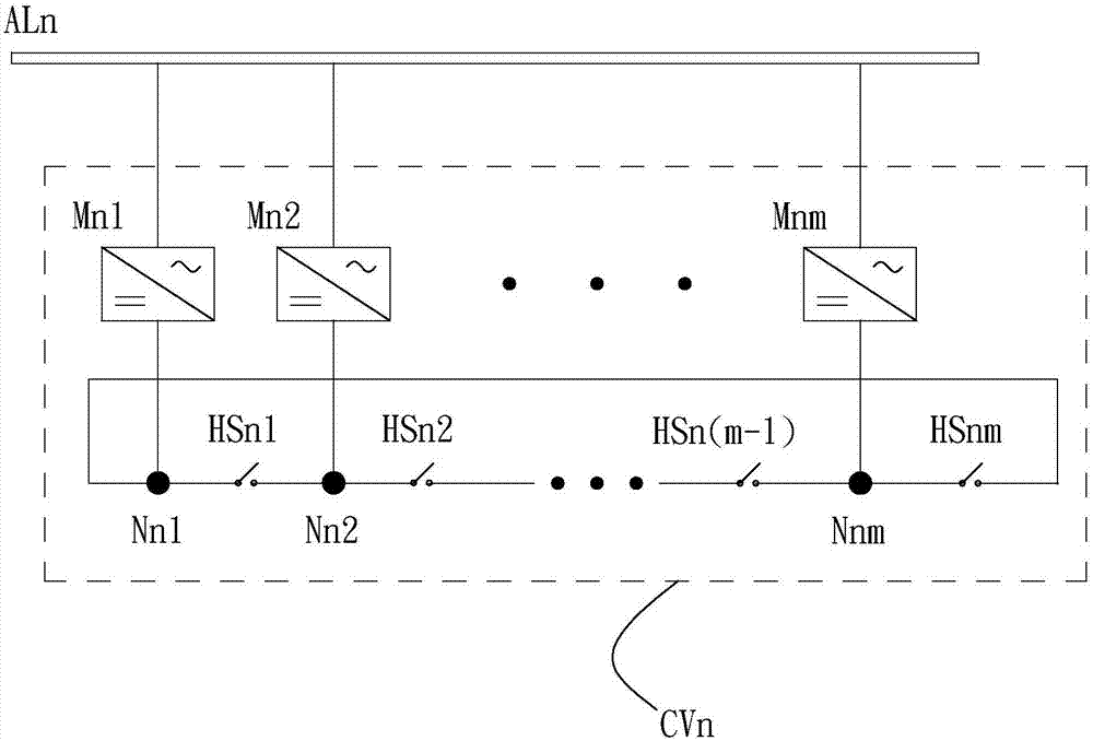
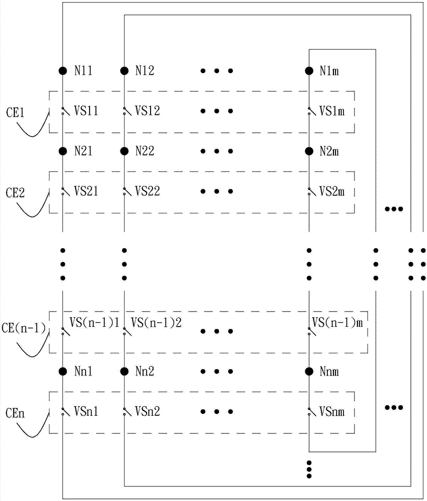
[0030] see Figure 1 to Figure 3 , is a ring-matrix multi-power stage parallel fast charging system 10 according to a preferred embodiment of the present invention, which is used to be installed in an ...


PUM


Abstract

The invention discloses an annular matrix type rapid charging system with a plurality of parallel power segments and a control method thereof. The annular matrix type rapid charging system is arranged in an electric vehicle charging station to output electric energy to electric vehicles. The annular matrix type rapid charging system with the plurality of parallel power segments is characterized by comprising a plurality of alternating-current buses, a plurality of conversion assemblies and a plurality of bridging assemblies, wherein the plurality of conversion assemblies are correspondingly connected with the alternating-current buses respectively; the bridging assemblies are connected with the conversion assemblies respectively; the conversion assemblies comprise a plurality of power modules and a plurality of transverse bridging switches; the alternating-current buses are connected with one another. By adopting the annular matrix type rapid charging system with the plurality of parallel power segments, corresponding nodes of the power modules are connected in a matrix form, and electric vehicle loads which are connected to the nodes can obtain higher input power conveniently and rapidly through connection matching among the nodes, so that the charging speeds of the electric vehicles which are connected with the annular matrix type rapid charging system with the plurality of parallel power segments are ensured, and meanwhile the investment of the power modules in the charging system is lowered.

Description

technical field [0001] The invention relates to the technical field of charging, in particular to an annular matrix multi-power section parallel fast charging system and a control method thereof. Background technique [0002] Electric vehicle charging station is a place to provide charging for electric vehicles. There are more or less electric vehicle charging piles in the charging station, and the charging piles are used to output electric energy to electric vehicles. There is a charging system in the charging station. The charging system is responsible for the conversion of electric energy and the distribution of power to each charging pile. The power module in the electric energy system is responsible for the conversion of AC and DC. The power distribution scheme of the existing charging system can be based on the power output of the charging pile. Requirements to adjust the number of power modules connected to the charging pile, limited by the existing power module depl...

Claims


Application Information

Patent Timeline
Patent Type & Authority Applications(China)
IPC IPC(8): H02J7/04B60L11/18
CPCB60L53/11B60L53/30B60L53/63H02J7/0071Y02T10/7072Y02T10/70Y02T90/12Y02T90/14
Inventor 李晓峰梁云龙
Owner EAST GRP CO LTD
Why Eureka
Try Eureka