Magnetic resonance equipment

A technology of magnetic resonance equipment and area, which is applied in magnetic resonance measurement, measurement using nuclear magnetic resonance imaging system, measurement of magnetic variables, etc., and can solve problems such as prolonging scanning time and increasing specific absorption rate.

Active Publication Date: 2020-01-21
GENERAL ELECTRIC CO
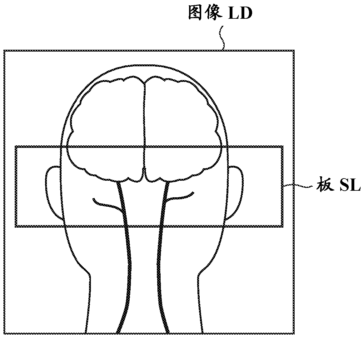
View PDF5 Cites 0 Cited by
  • Summary
  • Abstract
  • Description
  • Claims
  • Application Information

AI Technical Summary

Problems solved by technology

However, MT pulses have a large flip angle (eg, 900 degrees), which poses a problem of increased SAR when imaging a subject
Accordingly, when using MT pulses to execute a 3D TOF-MRA pulse sequence, it is necessary to extend the repetition time TR so that the upper limit of the specific absorption rate SAR is not exceeded, thereby causing the problem of prolonging the scan time required for executing the pulse sequence

Method used


Image

  • Magnetic resonance equipment
  • Magnetic resonance equipment
  • Magnetic resonance equipment

Examples


Embodiment Construction

[0033] Examples for carrying out the present invention will be described below, although the present invention is not limited thereto.

[0034] figure 1 is a schematic diagram of a magnetic resonance apparatus in one embodiment of the invention.

[0035] A magnetic resonance apparatus (hereinafter referred to as “MR apparatus”) 100 includes a magnet 2 , a gantry 3 and an RF receiving coil (hereinafter referred to as “receiving coil”) 4 .

[0036] The magnet 2 has a bore 21 therein through which the subject 13 is inserted. The magnet 2 includes a superconducting coil for generating a static magnetic field, a gradient coil for applying a gradient magnetic field, and an RF coil for applying RF pulses. Permanent magnets can be used instead of superconducting coils.

[0037] The stand 3 has a bracket 3a. The bracket 3 a is configured to be movable into the bore 21 . The subject 13 is transported into the bore 21 by the carriage 3a.

[0038] The receiving coil 4 is attached to...


PUM


Abstract

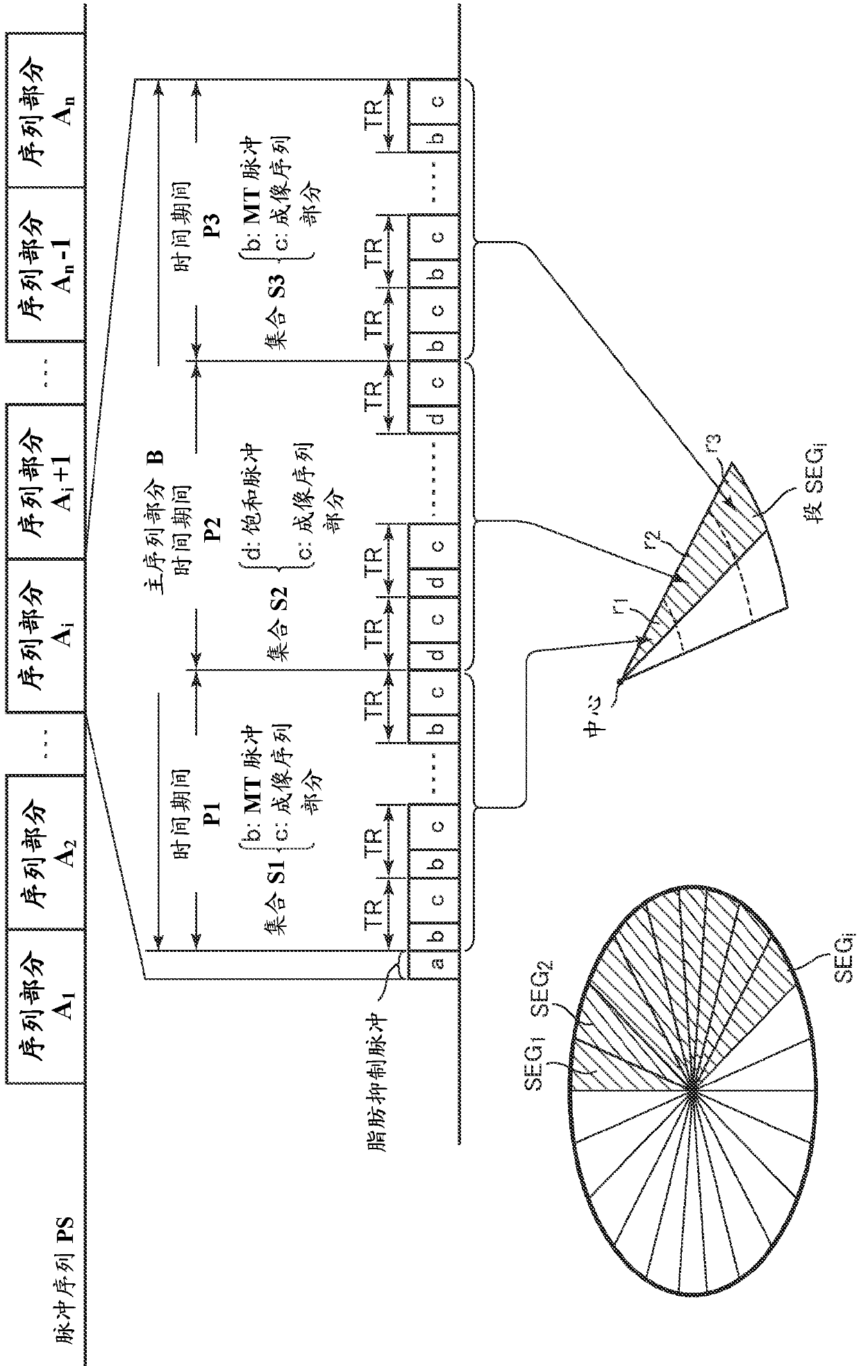
A magnetic resonance imaging apparatus comprises a scanning unit for performing a pulse sequence PS including a MT (Magnetization Transfer) pulse b for lessening signals from the cerebral parenchyma (white matter and gray matter). The scanning unit performs the pulse sequence PS in periods of time P1 and P3 in the pulse sequence PS so that the MT pulse b is applied every repetition time TR, while it performs the pulse sequence PS in a period of time P2 in the pulse sequence PS so that no MT pulse b is applied.

Description

[0001] Cross References to Related Applications [0002] This application claims priority from Japanese Patent Application No. 2014-262969 filed on December 25, 2015, which is hereby incorporated by reference in its entirety. Background technique [0003] The invention relates to a magnetic resonance apparatus executing a pulse sequence comprising RF pulses for causing a transfer of magnetization. [0004] Known techniques for presenting blood in the head and neck include a method that involves setting up a slab in the head and neck and using 3D time-of-flight MR angiography (TOF -MRA) to acquire data from the plate. In the 3DTOF-MRA method, the inflow effect caused by blood flowing into the plate from an area outside the plate enables visualization of blood flowing in the plate. [0005] However, the plate contains not only blood as the object to be presented, but also various background tissues that are not the object to be presented. Therefore, complete suppression of th...

Claims


Application Information

Patent Timeline
Patent Type & Authority Patents(China)
IPC IPC(8): G01R33/28G01R33/48G01R33/483G01R33/56
CPCG01R33/288G01R33/4818G01R33/4838G01R33/5605G01R33/482G01R33/4824G01R33/543G01R33/5607G01R33/5635G01R33/561
Inventor M.米尤施N.塔凯
Owner GENERAL ELECTRIC CO
Why Eureka
Try Eureka