
Welding pin taking device for bottom spot-welding

A technology of welding pins and spot bottoms, which is applied in the direction of auxiliary devices, welding equipment, auxiliary welding equipment, etc., can solve the problems of reduced battery life, desoldering of tabs, high internal resistance, etc., and achieves a balance between welding production quality and efficiency, Solve the effect of desoldering

Inactive Publication Date: 2017-09-05
JIANGSU SUNPOWER
View PDF5 Cites 2 Cited by
  • Summary
  • Abstract
  • Description
  • Claims
  • Application Information

AI Technical Summary

Problems solved by technology

At present, lithium-ion batteries are divided into metal shells and soft packages. The negative tabs of cylindrical lithium-ion batteries need to be welded to the bottom of the shell to form an electrical circuit at the bottom. If the bottom is not welded properly, the battery will easily cause high vibration in the later use Internal resistance, excessive self-discharge; or open circuit, unusable and other adverse factors, thereby reducing the service life of the battery and scrapping it early
The existing lithium battery welding production line adopts multi-channel parallel welding: multiple welding pins are manually placed in multiple battery cases, and multiple welding pins are welded at the same time, and the welding pins can be taken out after welding. Phenomenon, it is easy to cause the desoldering of the tab during the needle removal process, which will cause hidden dangers in production quality or lead to direct scrapping

Method used


Image

  • Welding pin taking device for bottom spot-welding

Examples


Embodiment Construction

[0008] Further description will be made below in conjunction with drawings and embodiments.

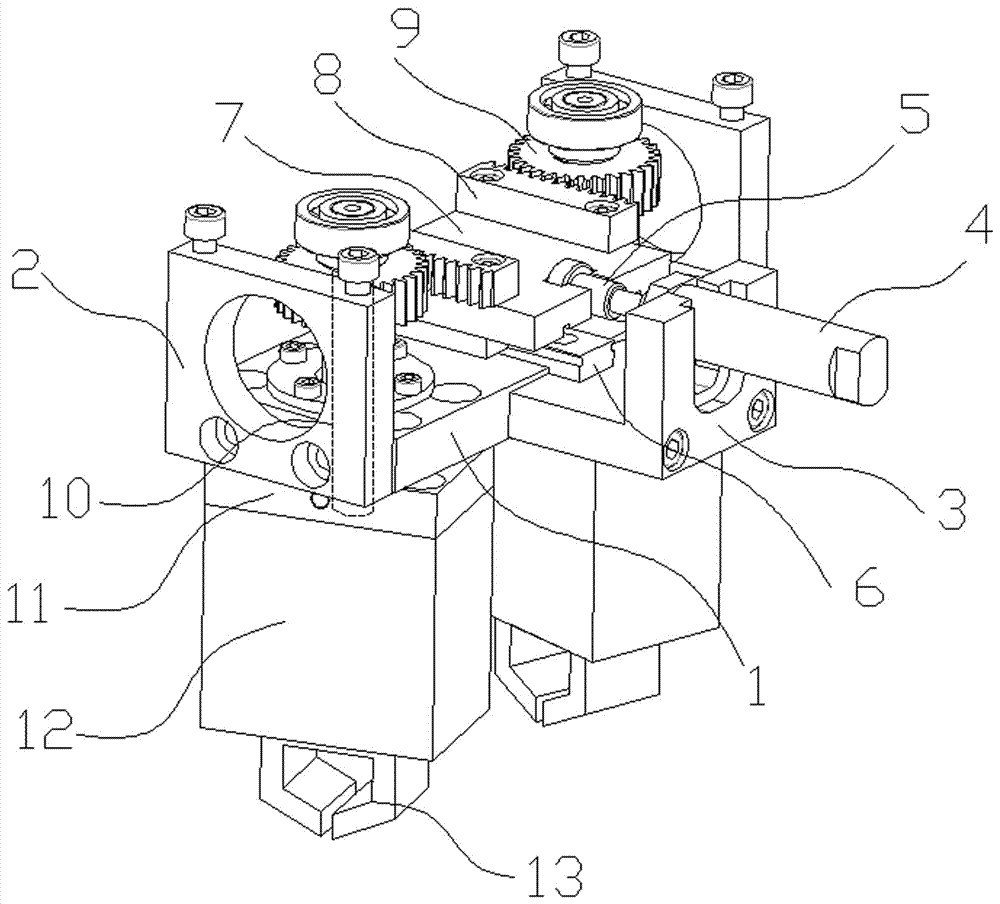
[0009] figure 1 As shown: a device for spot bottom welding and taking welding needles includes a bottom plate 1, a side plate 2, a cylinder support seat 3, a swing cylinder 4, a cylinder connector 5, a linear track 6, a track connecting plate 7, a rack 8, a gear 9, Rotating shaft 10, pneumatic finger connecting seat 11, pneumatic finger 12, clamp 13. The machine base consists of the bottom plate 1 and the side plates 2 on both sides of the bottom plate 1. The machine base is connected to the lithium battery production line rack in a state of lifting up and down after the cylinder is taken out. The cylinder support seat 3 is connected to the bottom plate 1, and the swing cylinder 4 is supported on the cylinder. On the support seat 3, the linear track 6 is arranged on the bottom plate 1, and the track connecting plate 7 is arranged on the linear track 6 and is connected to the swing cy...


PUM


Abstract

The invention relates to a welding pin taking device for bottom spot-welding. The welding pin taking device comprises a machine base, a cylinder supporting seat, an oscillating cylinder, a cylinder connector, a taking cylinder, a track connecting plate, linear tracks, racks, gears, rotary shafts, pneumatic finger connecting seats and pneumatic fingers. The machine base is connected to a lithium battery production line rack in an ascending and descending state through the taking cylinder. The cylinder supporting seat is connected to the machine base. The oscillating cylinder is supported by the cylinder supporting seat. The linear tracks are arranged on the machine base. The track connecting plate is arranged on the linear tracks and connected with the oscillating cylinder through the cylinder connector and is driven to move along the linear tracks by the oscillating cylinder. The racks are connected to the track connecting plate. The gears are arranged on the rotary shafts in a penetrating mode. The rotary shafts are supported by the machine base and are connected to the machine base in a penetrating mode. The racks are engaged with the corresponding gears. The lower ends of the rotary shafts penetrate through the machine base and are connected with the corresponding pneumatic finger connecting seats. The pneumatic fingers are connected to the lower portions of the corresponding pneumatic finger connecting seats.

Description

technical field [0001] The invention relates to a battery production device, in particular to a device for taking welding pins for spot bottom welding. Background technique [0002] With the development of society, the aggravation of environmental pollution and the depletion of traditional energy sources, people's awareness of environmental protection is getting stronger and stronger. Lithium-ion batteries have many advantages such as high energy density, high voltage platform, small self-discharge, and environmental protection, and have become the first choice for green energy. At present, lithium-ion batteries are divided into metal shells and soft packages. The negative tabs of cylindrical lithium-ion batteries need to be welded to the bottom of the shell to form an electrical circuit at the bottom. If the bottom is not welded properly, the battery will easily cause high vibration in the later use Internal resistance, excessive self-discharge; or open circuit, unusable a...

Claims


Application Information

Patent Timeline
Patent Type & Authority Applications(China)
IPC IPC(8): B23K37/00H01M10/058H01M10/0525H01M2/26
CPCB23K37/00H01M10/0525H01M10/058H01M50/531Y02E60/10Y02P70/50
Inventor 孙常尚宋泽斌杨晓旭郭序元王建兵
Owner JIANGSU SUNPOWER
Learn More