Machine tool with rear off-machine positioning and automatic loading-unloading functions

A technology of automatic loading and unloading and external positioning, applied in metal processing and other directions, can solve problems such as unfavorable observation, operation and maintenance of processing areas, reduced service life, complex machine tool structure, etc. The effect of spaciousness

Pending Publication Date: 2017-09-05
BEIJING JINGDIAO GRP CO LTD
View PDF7 Cites 3 Cited by
  • Summary
  • Abstract
  • Description
  • Claims
  • Application Information

AI Technical Summary

Problems solved by technology

In existing machine tools of this type, the automatic loading and unloading device and the processing area of ​​the machine tool often overlap and distribute. On the one hand, the internal structure of the machine tool is complicated, which is not conducive to the observation, operation and maintenance of the processing area; on the other hand, some parts in the loading and unloading device Easily damaged by cutting fluid during processing, thus reducing service life
At the same time, this overlapping structure is easy to influence each other during product preparation and processing, which in turn affects the further improvement of production efficiency

Method used


Image

  • Machine tool with rear off-machine positioning and automatic loading-unloading functions
  • Machine tool with rear off-machine positioning and automatic loading-unloading functions
  • Machine tool with rear off-machine positioning and automatic loading-unloading functions

Examples


Embodiment Construction

[0018] The present invention will be further described in detail below in conjunction with the accompanying drawings and specific embodiments.

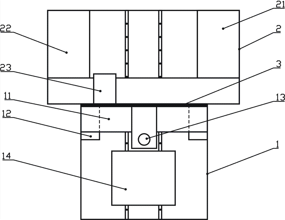
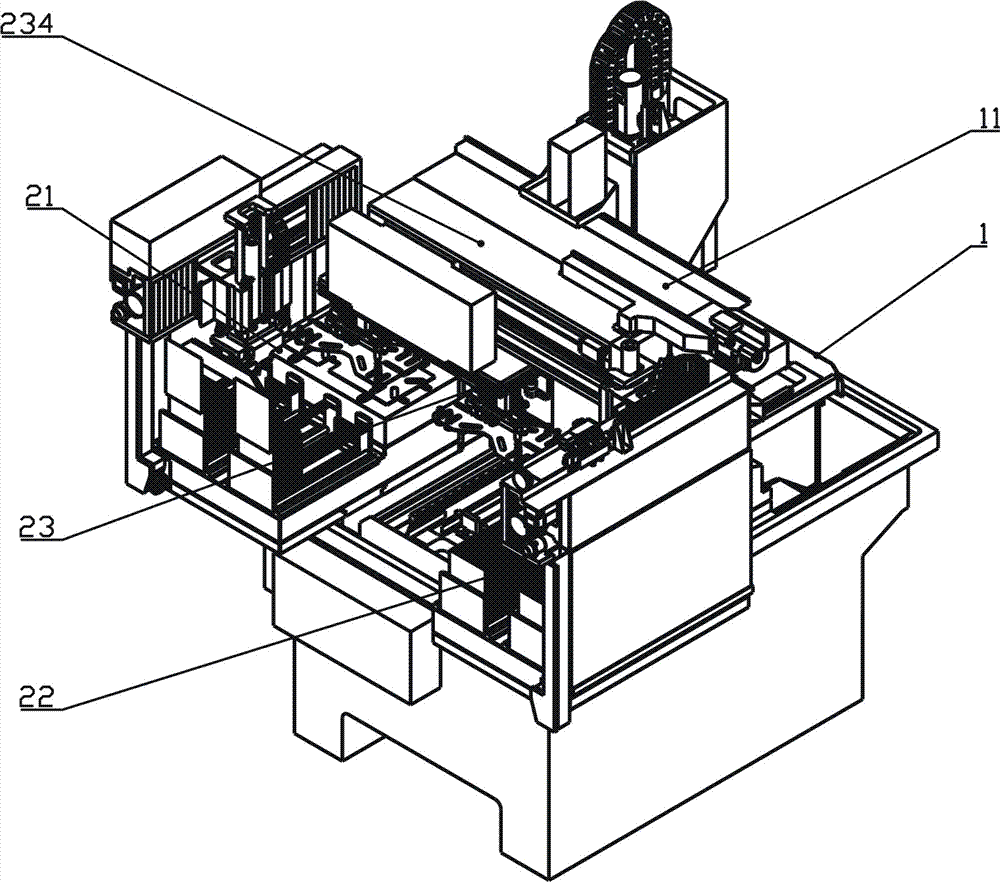
[0019] combine figure 1 and figure 2 As shown, a rear-type external positioning automatic loading and unloading machine tool of the present invention includes a machine tool processing part 1 and an automatic loading and unloading part 2. Both the machine tool processing part 1 and the automatic loading and unloading part 2 are installed on the machine bed, and can automatically The material section 2 is located behind the machine tool processing section 1, and is isolated and protected by an automatic door 3. The machine tool processing section 1 is composed of a beam 11 , a column 12 , an electric spindle 13 and a worktable 14 , and the worktable 14 can move between the machine tool processing section 1 and the automatic loading and unloading section 2 . The automatic loading and unloading part 2 is made up of a feeding area 21, ...


PUM


Abstract

The invention belongs to the technical field of numerical-control automatic machining, and particularly relates to machine tool with rear off-machine positioning and automatic loading-unloading functions. The machine tool comprises a machine tool machining part and an automatic loading-unloading part, wherein both the machine tool machining part and the automatic loading-unloading part are mounted on a machine tool body; the automatic loading-unloading part is positioned at the rear of the machine tool machining part, and is isolated and protected through an automatic door; the machining tool machining part comprises a cross beam, a vertical column, an electric spindle and a workbench; the workbench can move between the machine tool machining part and the automatic loading-unloading part; the automatic loading-unloading part comprises a loading zone, an unloading zone and a handling manipulator; the loading zone and the unloading zone are mounted in a left-right symmetric manner; the loading zone comprises a loading positioning table; the unloading zone comprises an unloading transfer table; and the handling manipulator is arranged between the loading zone and the unloading zone, and can move between the loading positioning table and the unloading transfer table. The machine tool provided by the invention is simple in structure; the loading-unloading operation, the material preparation operation and the positioning operation are all performed in an off-machine manner; the automatic loading-unloading part and the machine tool machining part, namely a machining zone, are prevented from influencing each other; the auxiliary machining time is effectively shortened; and the production efficiency is improved.

Description

technical field [0001] The invention belongs to the technical field of numerical control automatic processing, and in particular relates to a post-mounted automatic loading and unloading machine tool with external positioning. Background technique [0002] With the development of CNC machining technology and the improvement of market processing requirements, CNC machine tools with automatic loading and unloading functions are gradually favored by the market. This type of machine tool can realize the automatic handling, positioning and clamping of workpieces, which can shorten the auxiliary processing time of workpieces to a certain extent, improve production efficiency, and can also improve the consistency and accuracy of workpiece clamping and positioning. Compared with traditional CNC Machine tools can realize positioning and processing of products more quickly, high-speed, high-efficiency, and high-precision. In existing machine tools of this type, the automatic loading ...

Claims


Application Information

Patent Timeline
Patent Type & Authority Applications(China)
IPC IPC(8): B23Q7/00B23Q7/04
CPCB23Q7/00B23Q7/008B23Q7/043
Inventor 邓宇魏志军王岱韩银平宋非平
Owner BEIJING JINGDIAO GRP CO LTD
Why Eureka
Try Eureka