Supporting and retaining structure of existing retaining wall straight penetrated by large-span tunnel and construction method thereof

A technology of retaining structure and construction method, which is applied in the direction of foundation structure engineering, excavation, sheet pile wall, etc., can solve the problems of increasing sliding force, affecting the appearance, and limited tension of anchor cables, etc., and achieves reducing deformation and strengthening reinforcement Good effect and load-bearing capacity, reinforcement effect

Active Publication Date: 2017-09-05
CHONGQING UNIV +1
View PDF7 Cites 11 Cited by
  • Summary
  • Abstract
  • Description
  • Claims
  • Application Information

AI Technical Summary

Problems solved by technology

Grouting is mainly to reduce deformation by improving the strength characteristics of rock and soil. It is suitable for the development of cracks, loose rock and soil, insufficient filling compaction, and insufficient structural base resistance. For structures that have bulging deformation, cracking and grouting The grout cannot improve the stability of the sliding body but increases the sliding force and other diseases. Not only has no effect but aggravates the diseases, the road surface grouting construction of the municipal road section not only interferes with traffic operations but also affects the surrounding environment
The pulling force of anchor cables (rods) is limited, and it is not suitable for structures that are subject to large forces and require small deformations, especially large deformations at tunnel exits and busy road slope support structures mean structural damage, which seriously threatens safety
Corbels and anti-slide piles are commonly used outside the existing st

Method used


Image

  • Supporting and retaining structure of existing retaining wall straight penetrated by large-span tunnel and construction method thereof
  • Supporting and retaining structure of existing retaining wall straight penetrated by large-span tunnel and construction method thereof
  • Supporting and retaining structure of existing retaining wall straight penetrated by large-span tunnel and construction method thereof

Examples


Embodiment Construction

[0054] Hereinafter, the preferred embodiments of the present invention will be described in detail with reference to the accompanying drawings.

[0055] The reference signs in the drawings of the specification include:

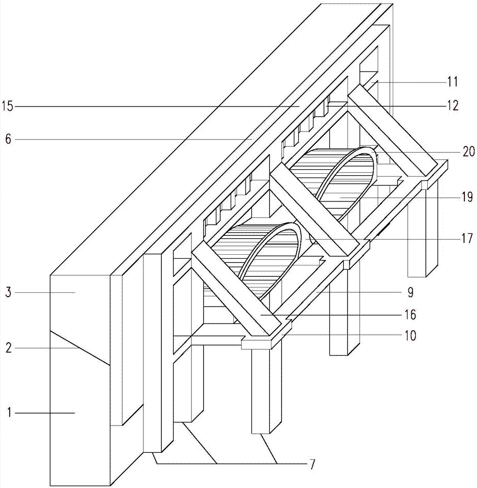
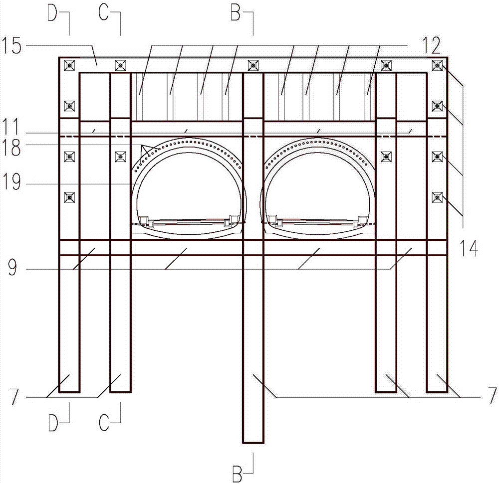
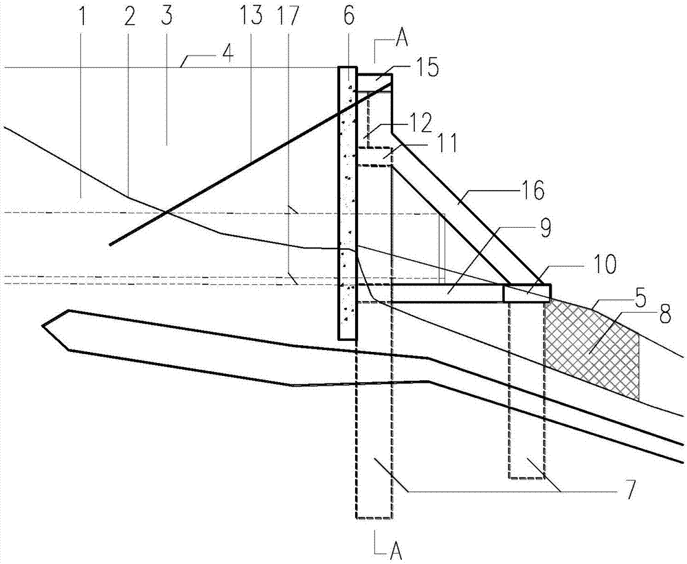
[0056] Bedrock bearing body 1, potential slip surface 2, sliding body 3, slope top road surface 4, ground line 5, supporting structure 6, anti-slide pile 7, grouting reinforcement 8, ground connecting beam 9, pile end cap 10. Coupling beam 11, rib column 12, anchor cable 13, anchor pull head 14, crown beam 15, diagonal brace 16, multi-arch tunnel partition wall 17, advanced small conduit 18, tunnel lining structure 19, tunnel opening 20.

[0057] Such as figure 1 , figure 2 , image 3 , Figure 4 with Figure 5 The large-span tunnel shown is passing through the retaining structure of the existing retaining wall. This example is the exit section of a multi-arch tunnel. The tunnel goes under a municipal road with heavy traffic. The entrance mileage is ZK5+494.461 and ...


PUM


Abstract

The invention belongs to the technical field of tunnel engineering and particularly relates to a supporting and retaining structure of an existing retaining wall straight penetrated by a large-span tunnel and a construction method thereof. The supporting and retaining structure comprises two rows of anti-skid piles, a ground coupling beam, coupling beams, a top beam, inclined struts, an anchor stay cable structure and a grouting reinforcement body. The two rows of anti-skid piles are mounted on the outer side of the supporting and retaining structure. The front row of anti-skid piles are at a certain distance from the supporting and retaining structure and are connected with one another through the ground coupling beam. The rear row of anti-skid piles are tightly attached to the supporting and retaining structure and connected with one another through the top beam, the coupling beams and the ground coupling beam. The two rows of the anti-skid piles are connected through the ground coupling beam and the inclined struts to form an overall frame structure. The rear row of anti-skid piles are provided with opposite-pull anchor stay cables. Rock and soil masses on the stressed sides of the peripheries of the anti-skid piles are subjected to grouting reinforcement, and the bearing capacities of the rock and soil masses and the supporting and retaining structure are improved. The supporting and retaining structure is applicable to an entrance and an exit of the large-span tunnel and a tunnel entrance heading slop with the requirement of small deformation, the reinforcing effect is guaranteed, and traffic operation is not blocked.

Description

Technical field [0001] The invention belongs to the technical field of tunnel engineering, and particularly relates to a supporting structure and a construction method for a large-span tunnel passing through an existing retaining wall. Background technique [0002] Since the 21st century, with the construction of my country's high-speed railway network, expressway network, high-grade highway network and urban municipal road network, my country's transportation engineering infrastructure construction has been booming. In my country’s inland areas where there are many mountains, houses, roads, etc. are mostly built on the slopes after reinforcing the slope with retaining walls according to local conditions. The construction of higher road networks often adopts the form of tunnel structure crossing the mountain and slope sloping, which involves the entrance and exit of the tunnel. There is a problem with the existing retaining wall structure when the section passes through houses, ro...

Claims


Application Information

Patent Timeline
IPC IPC(8): E02D17/20E02D27/14E02D5/74
CPCE02D5/74E02D17/207E02D27/14
Inventor 钟祖良刘新荣任玉琪傅晏杨忠平夏彪
Owner CHONGQING UNIV
Why Eureka
Try Eureka