Novel high power LED lamp body

A LED lighting, high-power technology, applied in semiconductor devices of light-emitting elements, lighting and heating equipment, fixed lighting devices, etc., can solve the problems of large differences in lamp bodies, affecting the advantages of LEDs, affecting the heat dissipation efficiency of lamps, etc. Low cost, easy production and assembly management, and compact structure

Active Publication Date: 2017-09-05
HUNAN MINGHE OPTO TECH
View PDF6 Cites 5 Cited by
  • Summary
  • Abstract
  • Description
  • Claims
  • Application Information

AI Technical Summary

Problems solved by technology

[0005] 3. There are relatively large differences in the assembled lamp body;
[0006] 4. Part of the large amount of heat generated by the light source is stacked on the lamp body or

Method used


Image

  • Novel high power LED lamp body
  • Novel high power LED lamp body
  • Novel high power LED lamp body

Examples


Embodiment 1

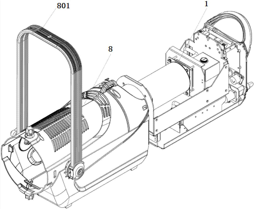
[0093] Such as Figure 1-10 As shown, this embodiment provides a high-power LED imaging lamp lamp body, including:

[0094] Including: lamp housing 8, optical path cooling combination system 1;

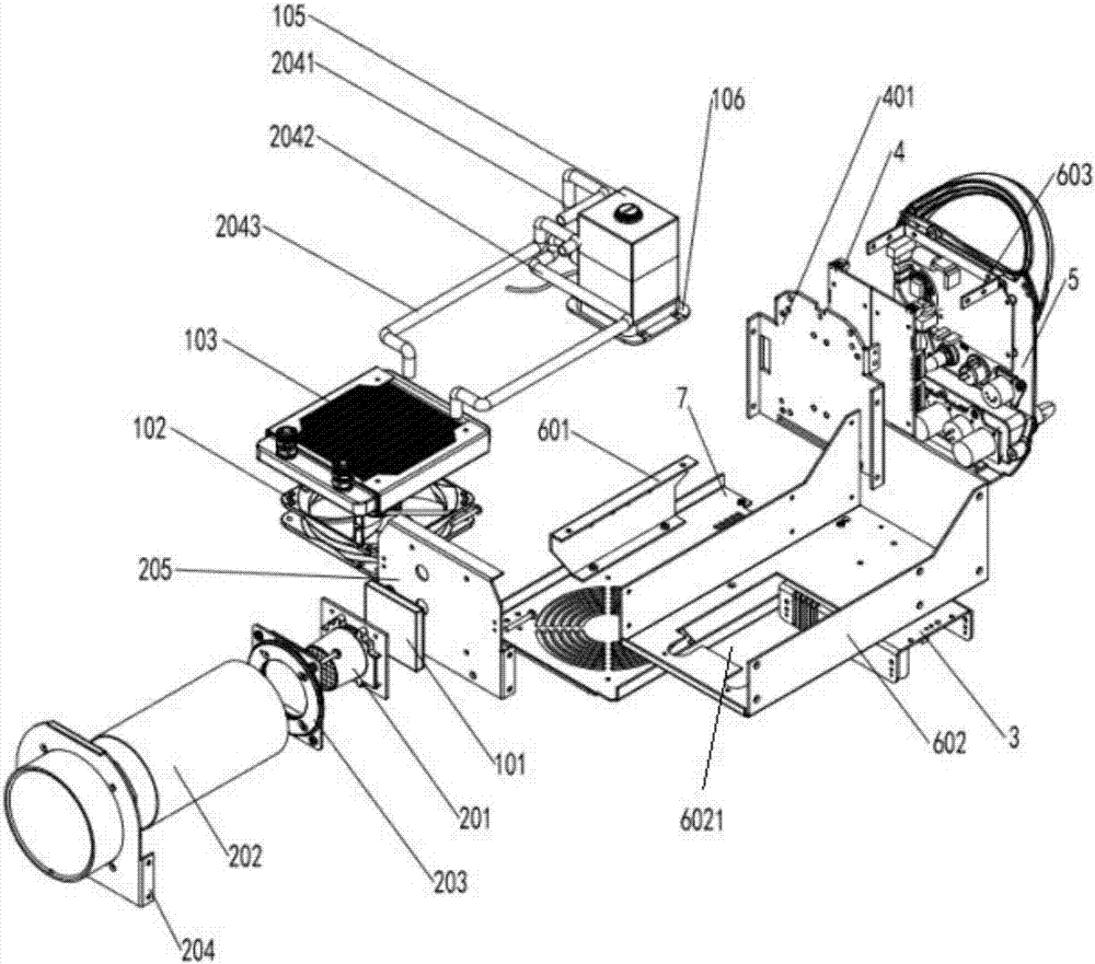
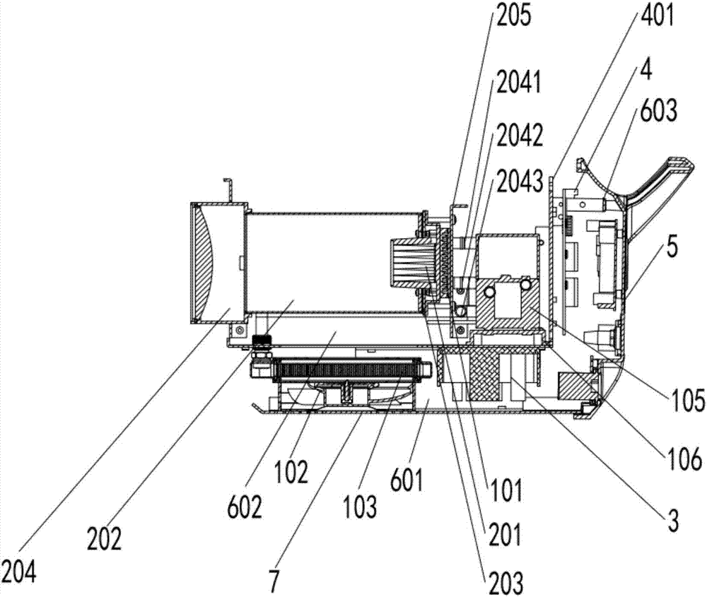
[0095] The optical path heat dissipation combination system 1 includes a base and an optical path module, a liquid-cooled air-cooled heat dissipation module, a power supply module, a drive module, and a main control display module arranged on the base in sequence;

[0096]Ribs are provided on both sides of the bottom of the base, and guide rails are provided on both sides of the bottom of the lamp housing. The ribs and the guide rails cooperate with each other, so that the base can be installed in the lamp housing 8 along the guide rails; The plug-in connection between the shell 8 and the optical path heat dissipation combination system 1;

[0097] The base includes a bottom substrate 7, two brackets one 601, two brackets 602, and three brackets 603; the two sides of the bottom of t...

Embodiment 2

[0142] Such as Figure 11-13 As shown, the difference between this embodiment and embodiment 1 is:

[0143] When the circulation pipeline 1033 adopts metal pipes such as aluminum pipes or copper pipes, it can be set as follows according to actual needs Figure 11 Metal circulation pipes of different shapes as shown; or, combined pipes with metal pipes or circulation lines embedded with profiled radiators.

[0144] The groove cylinder 10131 inside the cover plate 1013 of the heat absorbing device 101 in Embodiment 1 can also be set as an annular guide groove 10131 ′, and the boss cylinder 10111 in the heat absorbing device main body 1011 and the annular guide groove inside the cover plate 1013 The flow channels 10131' form interconnected flow channels. On the one hand, the boss cylinder 10111 and the annular diversion groove 10131' can increase the heat dissipation area in the cavity; on the other hand, the superconducting liquid can be shunted, so that the superconducting li...


PUM


Abstract

The invention discloses a novel high power LED lamp body comprising a lamp shell and a light path heat dissipation combined system. The light path heat dissipation combined system comprises a base, a light path module, a liquid cooling and air cooling heat dissipation module, a power source module, a driving module and a main control display module, wherein the light path module, the liquid cooling and air cooling heat dissipation module, the power source module, the driving module and the main control display module are arranged on the base in sequence. The base is mounted inside the lamp shell in the mode that the base can be pulled out and inserted along a guide rail, so that pull-inserting type connection of the lamp shell and the light path heat dissipation combined system is achieved. The liquid cooling and air cooling heat dissipation module comprises a heat absorption device, a liquid cooling heat dissipation device, a fan, a plurality of liquid cooling pipelines and a liquid circulation pump. The liquid circulation pump, the heat absorption device and the liquid cooling heat dissipation device are sequentially connected through the multiple liquid cooling pipelines. The LED lamp body can be widely applied to a high power LED imaging lamp and a spotlight. The novel high power LED lamp body is compact in structure, convenient to overhaul, large in power, good in lighting effect, convenient to detach, mount and overhaul, good in heat dissipation capacity and long in service life.

Description

technical field [0001] The invention relates to the technical field of high-power LED lamps, in particular to a lamp body of a high-power LED lamp. Background technique [0002] As we all know, LED is a new type of solid-state cold light source, which has the advantages of small size, long life, high luminous efficiency, energy saving and environmental protection. High-power LED is one of the hot spots of research and application in recent years, especially after the emergence of high-power LED chips, it has been widely and rapidly applied in various lighting applications, and has a great tendency to replace traditional lighting. In the current LED lamps, various complex parts are assembled in disorder, including: light source, heat sink, drive, control, power supply and other structural components. The disadvantage of this design is: [0003] 1. After the lamp fails, it is inconvenient to find and analyze the cause, which affects the efficiency of maintenance and assembly;...

Claims


Application Information

Patent Timeline
IPC IPC(8): F21S8/00F21V5/04F21V23/00F21V29/58F21V29/67F21V29/70F21Y115/10
CPCF21S8/00F21V5/045F21V23/003F21V29/59F21V29/67F21V29/70F21Y2115/10
Inventor 杨勉傅高武傅高鹏
Owner HUNAN MINGHE OPTO TECH
Why Eureka
Try Eureka